SPI
1. SPI Subsystem
In the Linux operating system, the SPI subsystem is a critical driver framework for managing and controlling various external devices connected via the SPI bus. More details about the SPI subsystem can be found in <Linux Kernel Source>/Documentation/spi. The key components of the SPI subsystem are:
- sysfs Interface: The SPI subsystem provides a set of files and directories via sysfs for configuring and managing SPI buses and devices. These files and directories are located under
/sys/class/spi_masterand/sys/bus/spi/devices, allowing users to view and modify SPI device attributes. - Device Nodes: Each connected SPI device creates a device node under the
/devdirectory, enabling user-space programs to communicate with the device using standard file I/O operations. Typically, these device nodes are named/dev/spidevX.Y, where X represents the SPI bus number, and Y represents the SPI device number.
2. Viewing SPI (Shell)
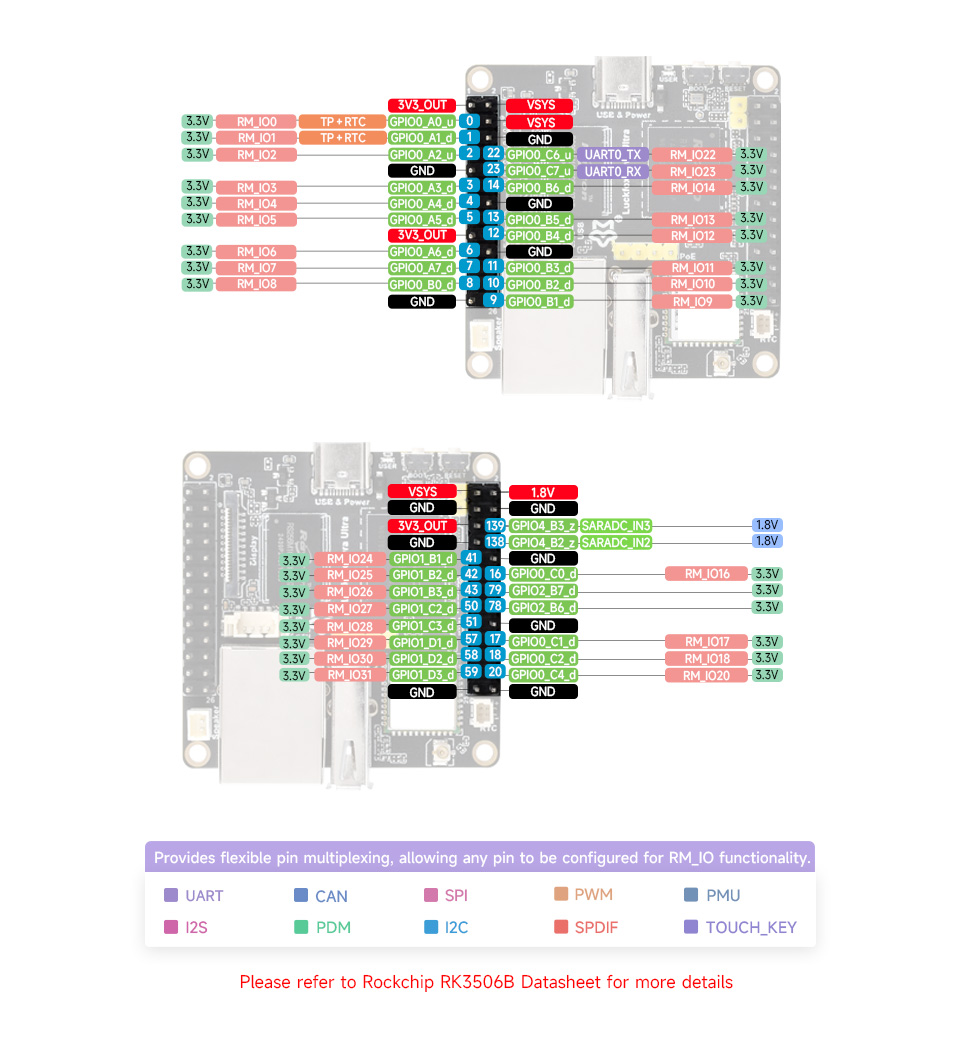
2.1 Pin Distribution
- Luckfox Lyra Ultra/Ultra W Pin Diagram:
2.2 Viewing Devices
In the /sys/bus/spi/devices directory, each SPI device has its own folder. These folder names typically include "spi" and the device number, such as /sys/bus/spi/devices/spi0.0, which represents device 0 on SPI bus 0. To view existing SPI buses in the system, use the following command:
# ls /sys/bus/spi/devices/
spi2.0  spi0.0
3. SPI Communication (Python Program)
3.1 Complete Code
The following program demonstrates SPI communication.
import spidev

def main():
    tx_buffer = [ord(char) for char in "hello world!"]
    rx_buffer = [0] * len(tx_buffer)

    try:
        spi = spidev.SpiDev()
        spi.open(0, 0)
        spi.max_speed_hz = 1000000

        rx_buffer = spi.xfer2(tx_buffer[:])
        print("tx_buffer:\n\r", ''.join(map(chr, tx_buffer)))
        print("rx_buffer:\n\r", ''.join(map(chr, rx_buffer)))

    except Exception as e:
        print(f"An error occurred: {e}")

    finally:
        if spi:
            spi.close()

if __name__ == "__main__":
    main()
3.2 Opening SPI Device
This code uses the SpiDev class from the spidev library to create an SPI object. The open method specifies the SPI bus and device number (here, bus 0 and device 0). The maximum transfer rate is set to 1,000,000 Hz (1 MHz).
spi = spidev.SpiDev()
spi.open(0, 0)
spi.max_speed_hz = 1000000
3.3 Data Transmission and Reception
The xfer2 method performs SPI data transfer. The tx_buffer contains the data to be sent, and rx_buffer stores the received data. The tx_buffer[:] ensures the original buffer remains unchanged. The transmitted and received data are printed for user verification.
rx_buffer = spi.xfer2(tx_buffer[:])
print("tx_buffer:\n\r", ''.join(map(chr, tx_buffer)))
print("rx_buffer:\n\r", ''.join(map(chr, rx_buffer)))
3.4 Running the Program
Open the file using
nano, paste, and save the code:# nano i2c.pyRun the program:
# python3 i2c.pyExperimental Setup: Connect the SPI MOSI and MISO lines, then execute the program.

4. SPI Communication (C Program)
4.1 ioctl Function
在编写应用程序时需要使用ioctl函数设置spi相关配置,其函数原型如下
 #include <sys/ioctl.h>

 int ioctl(int fd, unsigned long request, ...);
Common request parameters include:
SPI_IOC_RD_MODE: Reads the current SPI communication mode.SPI_IOC_WR_MODE: Sets the SPI communication mode.SPI_IOC_RD_BITS_PER_WORD: Reads the number of bits per word.SPI_IOC_WR_BITS_PER_WORD: Sets the number of bits per word.SPI_IOC_RD_MAX_SPEED_HZ: Reads the maximum SPI bus speed.SPI_IOC_WR_MAX_SPEED_HZ: Sets the maximum SPI bus speed.SPI_IOC_MESSAGE(N): Performs SPI read/write operations.SPI_IOC_RD_LSB_FIRST: Reads the LSB-first setting.SPI_IOC_WR_LSB_FIRST: Sets the LSB-first setting.
4.2 Example Program
SPI communication can be achieved through the following program.
#include <stdio.h>
#include <stdlib.h>
#include <stdint.h>
#include <fcntl.h>
#include <unistd.h>
#include <linux/spi/spidev.h>
#include <sys/ioctl.h>

#define SPI_DEVICE_PATH "/dev/spidev0.0"

int main() {
    int spi_file;
    uint8_t tx_buffer[50] = "hello world!";
    uint8_t rx_buffer[50];

    // Open the SPI device
    if ((spi_file = open(SPI_DEVICE_PATH, O_RDWR)) < 0) {
        perror("Failed to open SPI device");
        return -1;
    }

    // Configure SPI mode and bits per word
    uint8_t mode = SPI_MODE_0;
    uint8_t bits = 8;
    if (ioctl(spi_file, SPI_IOC_WR_MODE, &mode) < 0) {
        perror("Failed to set SPI mode");
        close(spi_file);
        return -1;
    }
    if (ioctl(spi_file, SPI_IOC_WR_BITS_PER_WORD, &bits) < 0) {
        perror("Failed to set SPI bits per word");
        close(spi_file);
        return -1;
    }

    // Perform SPI transfer
    struct spi_ioc_transfer transfer = {
        .tx_buf = (unsigned long)tx_buffer,
        .rx_buf = (unsigned long)rx_buffer,
        .len = sizeof(tx_buffer),
        .delay_usecs = 0,
        .speed_hz = 1000000,  // SPI speed in Hz
        .bits_per_word = 8,
    };

    if (ioctl(spi_file, SPI_IOC_MESSAGE(1), &transfer) < 0) {
        perror("Failed to perform SPI transfer");
        close(spi_file);
        return -1;
    }

     /* Print tx_buffer and rx_buffer*/
    printf("\rtx_buffer: \n %s\n ", tx_buffer);
    printf("\rrx_buffer: \n %s\n ", rx_buffer);

    // Close the SPI device
    close(spi_file);

    return 0;
}
4.3 File Path
This line of code defines a macro to store the path to the SPI device file.
#define SPI_DEVICE_PATH "/dev/spidev0.0"
4.4 Opening the SPI Device
This section of code attempts to open the specified SPI device file.
// Open the SPI device
if ((spi_file = open(SPI_DEVICE_PATH, O_RDWR)) < 0) {
    perror("Failed to open SPI device");
    return -1;
}
4.5 Configuring SPI
This piece of code configures the SPI communication mode to SPI Mode 0 (clock polarity = 0, clock phase = 0) and sets the bits per word to 8, ensuring proper and consistent SPI communication.
// Configure SPI mode and bits per word
uint8_t mode = SPI_MODE_0;
uint8_t bits = 8;
if (ioctl(spi_file, SPI_IOC_WR_MODE, &mode) < 0) {
    perror("Failed to set SPI mode");
    close(spi_file);
    return -1;
}
if (ioctl(spi_file, SPI_IOC_WR_BITS_PER_WORD, &bits) < 0) {
    perror("Failed to set SPI bits per word");
    close(spi_file);
    return -1;
}
This section defines a spi_ioc_transfer structure variable named transfer, used to configure the SPI transfer parameters. It specifies the data buffers, transfer length, delay time, SPI speed (in Hz), and bits per word. This structure is passed to the SPI_IOC_MESSAGE ioctl function to execute the SPI transfer.
// Perform SPI transfer
struct spi_ioc_transfer transfer = {
    .tx_buf = (unsigned long)tx_buffer,
    .rx_buf = (unsigned long)rx_buffer,
    .len = sizeof(tx_buffer),
    .delay_usecs = 0,
    .speed_hz = 1000000,  // SPI speed in Hz
    .bits_per_word = 8,
};
4.6 Data Transmission and Reception
This code uses the ioctl function to perform the SPI transfer. The SPI_IOC_MESSAGE(1) macro specifies a single transfer, and the third parameter is the address of the transfer structure configured above. If the SPI transfer fails, an error message is displayed, and the SPI device file descriptor is closed.
if (ioctl(spi_file, SPI_IOC_MESSAGE(1), &transfer) < 0) {
    perror("Failed to perform SPI transfer");
    close(spi_file);
    return -1;
}
4.7 Cross-Compilation
Cross-compile the program. For setting up the cross-compilation environment, refer to the "Program Compilation" or "GPIO" sections.
Cross-compile the program. For setting up the cross-compilation environment, refer to the "Program Compilation" or "GPIO" sections.
# chmod +x spi
# ./spi
Experimental Results. Connect the SPI MOSI and MISO lines, then run the program:

5. Device Tree Overview
The device file path is located in
kernel-6.1/arch/arm/boot/dts/rk3506g-luckfox-lyra.dts, The device file path is located inspi0:&spi0 {
status = "okay";
pinctrl-names = "default";
pinctrl-0 = <&rm_io7_spi0_clk &rm_io6_spi0_mosi &rm_io5_spi0_miso>;
spidev@0 {
compatible = "rockchip,spidev";
spi-max-frequency = <10000000>;
reg = <0>;
};
};