5. SPI
5.1 Introduction
SPI stands for Serial Peripheral Interface, which is a high-speed, full-duplex, synchronous communication bus.
It operates in a master-slave mode, where typically one master device corresponds to one or more slave devices. It requires 4 wires for bidirectional data transfer and can be reduced to 3 wires for unidirectional data transfer.
The SPI bus consists of four physical connections: two data lines, one clock line, and a slave select line.
MOSI (Master Output/Slave Input) – The line through which the Core3566 sends data to the device (sensor).
MISO (Master Input/Slave Output) – The line through which the device sends data to the Core3566.
SCLK (Clock) – The clock signal line.
SS/CS (Slave Select/Chip Select) – The line used to select the device to which data is being sent.
Core3566 has two SPI interfaces, namely SPI1 and SPI3.
5.2 Enabling the SPI Interface
The process of enabling the SPI interface is similar to I2C. Simply select SPI.
┌────────────┤ luckfox Software Configuration Tool (luckfox-config) ├────────────┐
│                                                                                │
│         P1 SPI1 Enable/disable automatic loading of SPI1 kernel module         │
│         P2 SPI3 Enable/disable automatic loading of SPI3 kernel module         │
│                                                                                │
│                                                                                │
│                                                                                │
│                                                                                │
│                                                                                │
│                     <Select>                     <Back>                        │
│                                                                                │
└────────────────────────────────────────────────────────────────────────────────┘
Use the ls command to check if the enablement was successful:
linaro@linaro-alip:~$ ls /dev/spi*
/dev/spidev1.0  /dev/spidev1.1
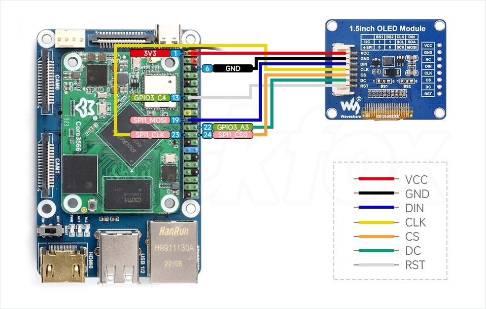
5.3 Hardware Connection
Pin connections for Core3566:
1.5inch OLED Module Core3566 Board Physical Pin Number Function VCC 3V3 Power input GND GND Power ground DIN SPI1_MOSI Master Output/Slave Input CLK SPI1_CLK SPI Clock signal CS SPI1_CS0 Chip select DC GPIO3_A3 Data/Command select RST GPIO3_C4 Reset Wiring Diagram.
5.4 Controlling with Python Program
Download the experiment code and run the program in the terminal:
cd ~/OLED_1in5/
sudo python3 OLED_1in5_spi.py