Using OpenPLC Editor
OpenPLC consists of OpenPLC Editor on the development computer and OpenPLC Runtime on the target device. OpenPLC Editor creates, builds, and uploads IEC 61131-3 programs. OpenPLC Runtime executes those programs on Luckfox Lyra PLC and provides access to its hardware.
This guide uses a ladder diagram (LD) to control onboard relay 0. It covers software installation, output mapping, project creation, and program upload.
1. Install OpenPLC Editor on the PC
- Open the OpenPLC download page and download OpenPLC Editor for your computer's operating system.
- Run the installer and complete the installation.
- Start OpenPLC Editor.
2. Install OpenPLC Runtime on Lyra PLC
Luckfox Lyra PLC runs Debian 12, so use the Linux installation procedure for OpenPLC Runtime.
-
Connect to Luckfox Lyra PLC over SSH.
-
Download the OpenPLC Runtime source and run the installer:
git clone https://github.com/Autonomy-Logic/openplc-runtime.gitcd openplc-runtimesudo ./install.sh -
Confirm that the service is running:
sudo systemctl status openplc-runtime.service
Use the following commands to manage the service:
sudo systemctl start openplc-runtime.service
sudo systemctl stop openplc-runtime.service
sudo systemctl restart openplc-runtime.service
3. Configure OpenPLC Runtime Output Mapping
3.1 OpenPLC Address Format
%QX0.0 identifies bit 0 of byte 0 in the PLC output area. It follows the IEC 61131-3 direct-address format:
| Address component | Meaning |
|---|---|
% | Direct-address prefix |
Q | Output area |
X | Bit data type, corresponding to BOOL |
0 (before the period) | Byte index, starting at 0 |
0 (after the period) | Bit index, starting at 0 |
This guide assigns the first relay, Relay0, to %QX0.0 and the second relay, Relay1, to %QX0.1. These addresses are assigned in the PLC program, not calculated from GPIO numbers.
3.2 Onboard Relay Mapping
%QX0.0 is a logical PLC address, while GPIO17 is a Linux GPIO number. A Runtime hardware plugin must associate the two. This guide configures the following mapping in the plugin:
| OpenPLC output | Linux GPIO | RK3506 pin | Enclosure label |
|---|---|---|---|
%QX0.0 | GPIO17 | GPIO0_C1 / RMIO_17 | RELAY0 |
%QX0.1 | GPIO18 | GPIO0_C2 / RMIO_18 | RELAY1 |
The board has two independently controlled relays, RELAY0 and RELAY1. Each relay has 1 normally open (NO) contact and 1 normally closed (NC) contact sharing a common (COM) terminal. Both control inputs are active high, with the following behavior:
| Control input | Relay coil | COM to NO | COM to NC |
|---|---|---|---|
Low (GPIO output 0) | De-energized; relay released | Open | Closed |
| High impedance or floating, held low by the pull-down resistor | De-energized; relay released | Open | Closed |
High (GPIO output 1) | Energized; relay actuated | Closed | Open |
"Active high" describes the relay control input, not a voltage output at the contacts. NO, NC, and COM are voltage-free mechanical switch contacts and do not supply voltage themselves. Follow the device terminal labels when wiring.
For Relay0, the program output reaches the physical relay through the following path:
3.3 Add the Lyra GPIO Plugin
OpenPLC Runtime v4 uses plugins for hardware access. The following plugin reads the output buffers for %QX0.0 and %QX0.1 and writes their states to GPIO17 and GPIO18.
Both relay control inputs have pull-down resistors. While a GPIO is high impedance or floating during power-on initialization, the pull-down keeps the coil de-energized. The plugin then writes low to the GPIO direction file to configure a low output and keep the relay released. A high output energizes the coil; no inversion of the control logic is required. The pull-down prevents floating-input actuation but does not override a high level actively driven by software.
-
Go to the OpenPLC Runtime directory and create the plugin directory:
cd ~/openplc-runtimesudo mkdir -p core/src/drivers/plugins/python/lyra_gpiosudo nano core/src/drivers/plugins/python/lyra_gpio/lyra_gpio.py -
Add the following code to
lyra_gpio.pyand save the file:Complete lyra_gpio.py source
#!/usr/bin/env python3import errnoimport osimport sysimport threadingimport timesys.path.insert(0, os.path.join(os.path.dirname(__file__), ".."))from shared import SafeBufferAccess, safe_extract_runtime_args_from_capsule# (byte index, bit index, Linux GPIO)RELAY_MAP = ((0, 0, 17), (0, 1, 18))GPIO_ROOT = "/sys/class/gpio"_buffer = None_worker = None_stop_event = threading.Event()def _write_text(path, value):with open(path, "w", encoding="ascii") as stream:stream.write(value)def _prepare_gpio(pin):gpio_dir = os.path.join(GPIO_ROOT, f"gpio{pin}")if not os.path.isdir(gpio_dir):try:_write_text(os.path.join(GPIO_ROOT, "export"), str(pin))except OSError as exc:if exc.errno != errno.EBUSY:raisefor _ in range(50):if os.path.isdir(gpio_dir):breaktime.sleep(0.01)if not os.path.isdir(gpio_dir):raise RuntimeError(f"GPIO{pin} was not exported")# Active-high control: initialize low to keep the coil de-energized._write_text(os.path.join(gpio_dir, "direction"), "low")def _set_gpio(pin, enabled):value_path = os.path.join(GPIO_ROOT, f"gpio{pin}", "value")_write_text(value_path, "1" if enabled else "0")def init(runtime_args_capsule):global _bufferruntime_args, error = safe_extract_runtime_args_from_capsule(runtime_args_capsule)if runtime_args is None:print(f"[lyra_gpio] Failed to access Runtime buffers: {error}")return False_buffer = SafeBufferAccess(runtime_args)if not _buffer.is_valid:print(f"[lyra_gpio] Invalid Runtime buffer: {_buffer.error_msg}")return Falsetry:for _, _, pin in RELAY_MAP:_prepare_gpio(pin)except Exception as exc:print(f"[lyra_gpio] GPIO initialization failed: {exc}")return Falsereturn Truedef _run():previous = {}while not _stop_event.wait(0.02):for byte_index, bit_index, pin in RELAY_MAP:value, error = _buffer.read_bool_output(byte_index, bit_index)if error != "Success":continueenabled = bool(value)if previous.get(pin) != enabled:_set_gpio(pin, enabled)previous[pin] = enableddef start_loop():global _worker_stop_event.clear()_worker = threading.Thread(target=_run, daemon=True)_worker.start()return 0def stop_loop():global _worker_stop_event.set()if _worker is not None:_worker.join(timeout=1)_worker = Nonefor _, _, pin in RELAY_MAP:try:_set_gpio(pin, False)except OSError:passdef cleanup():stop_loop() -
Edit
plugins.confin the Runtime root directory:sudo nano plugins.conf -
Add the following entry at the end of the file. The fields specify the plugin name, path, enabled state, and plugin type. Plugin type
0selects a Python plugin.lyra_gpio,./core/src/drivers/plugins/python/lyra_gpio/lyra_gpio.py,1,0 -
Restart the Runtime and inspect its log:
sudo systemctl restart openplc-runtime.servicesudo journalctl -u openplc-runtime.service -n 100 --no-pager
The Luckfox Lyra PLC WebUI can also control GPIO17 and GPIO18. Do not operate the relays from the WebUI while OpenPLC Runtime is controlling them, because the two applications may write different states.
4. Create and Upload a Ladder Diagram Program
4.1 Create a Project
-
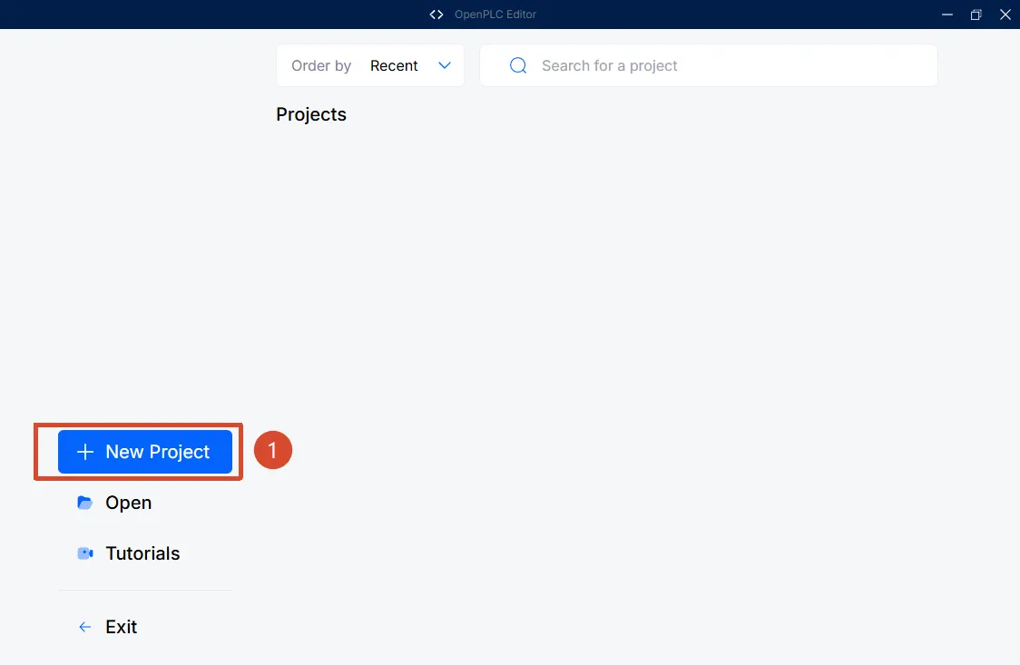
Start OpenPLC Editor and click "New Project".
-
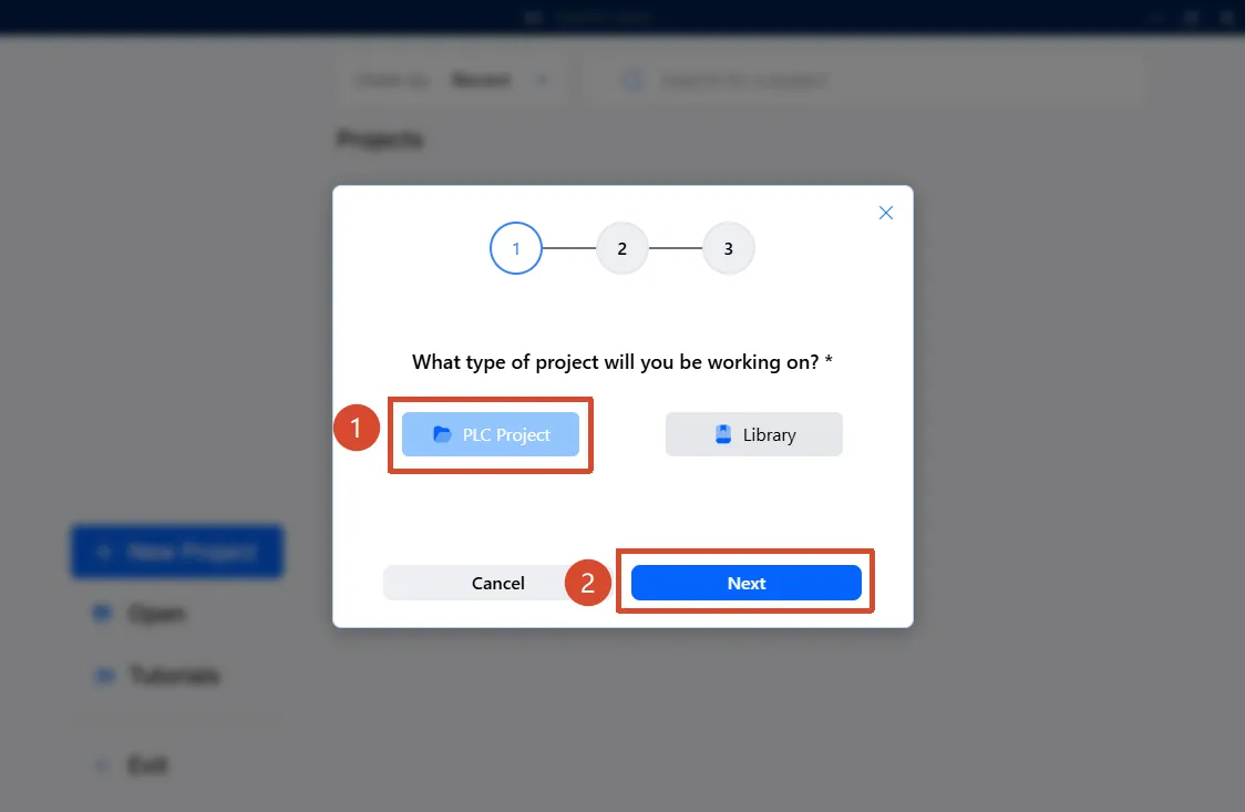
Select "PLC Project", then click "Next".
-
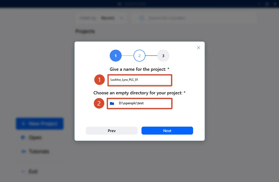
Enter a project name, select an empty project directory, and click "Next".
-
Select "Ladder Diagram" as the base program language and create the project.
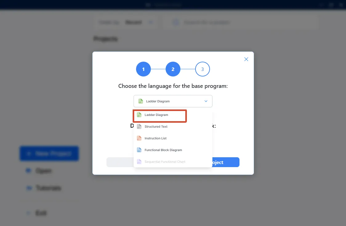
4.2 Write the Relay Control Program
This example uses a normally open contact with an initial value of TRUE to drive the Relay0 coil. Onboard relay 0 energizes when the program runs.
Do not connect mains voltage or a high-power load to the relay contacts during the initial run. The relay terminals provide voltage-free contacts, not 3.3 V GPIO signals. Listen for the relay to confirm actuation, or check the unloaded contacts with a multimeter in continuity mode.
-
Create the following variables:
Name Class Type Location Initial Value AlwaysOnLocal BOOL- TRUERelay0Output BOOL%QX0.0FALSE -
Add an
AlwaysOnnormally open contact and aRelay0coil to the ladder diagram:|----[ AlwaysOn ]----------------( Relay0 )----| -
Confirm that the Location of
Relay0is%QX0.0. The generated Structured Text (ST) should contain a declaration similar to this:Relay0 AT %QX0.0 : BOOL;
4.3 Connect to Luckfox Lyra PLC
-
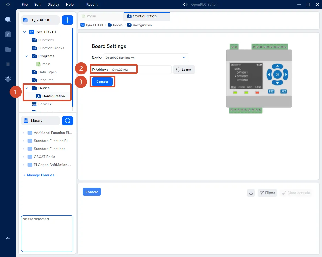
Open "Device" > "Configuration" in the project tree.
-
Enter the actual Luckfox Lyra PLC address in "IP Address", then click "Connect".
-
Enter the OpenPLC Runtime credentials.
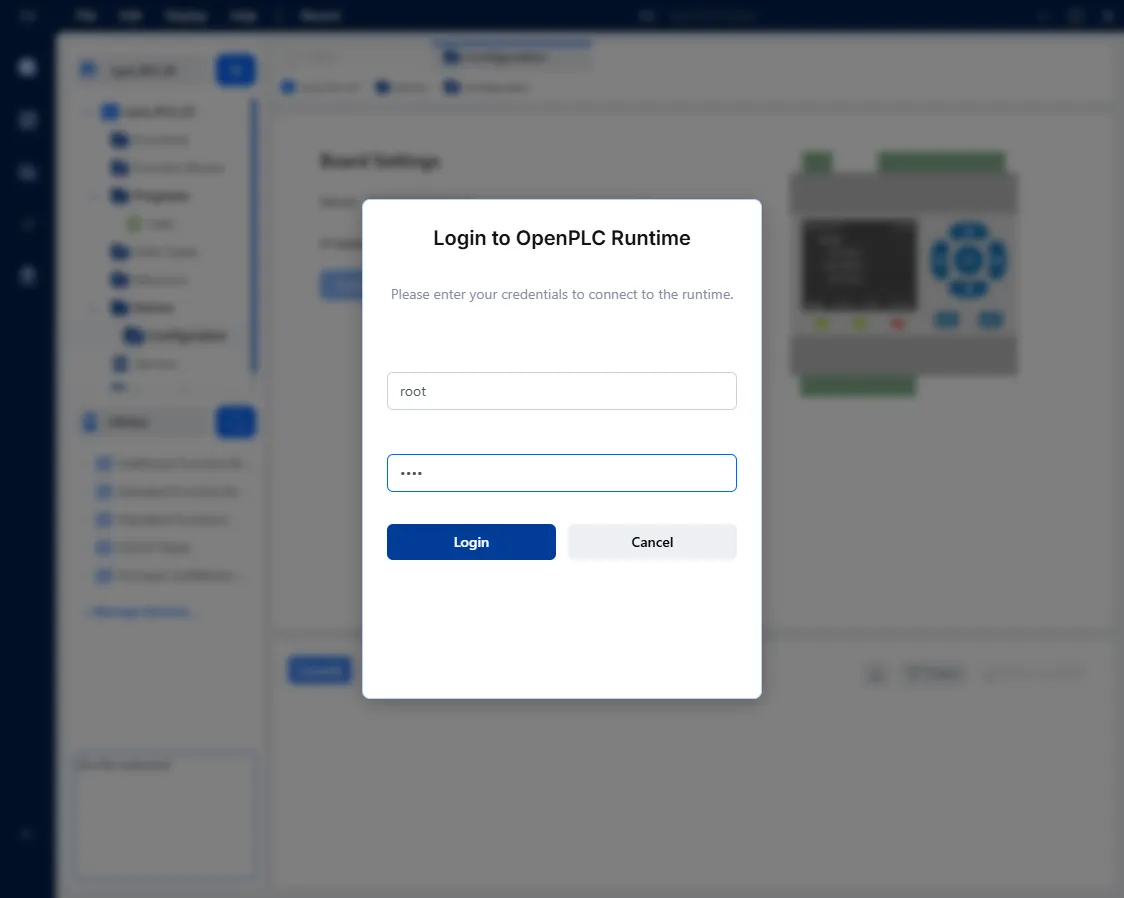 Runtime credentials
The default OpenPLC Runtime username and password are both
root. These credentials are separate from the Debian SSH account. If the Runtime password has been changed, enter the current password instead. -
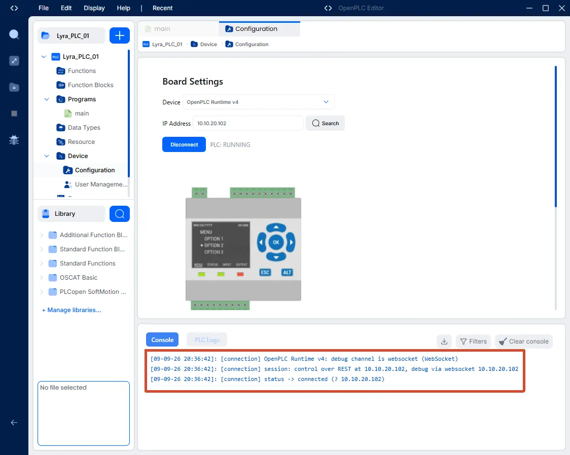
The connection is ready when the console reports "connected" and "PLC RUNNING".
4.4 Build and Upload the Program
-
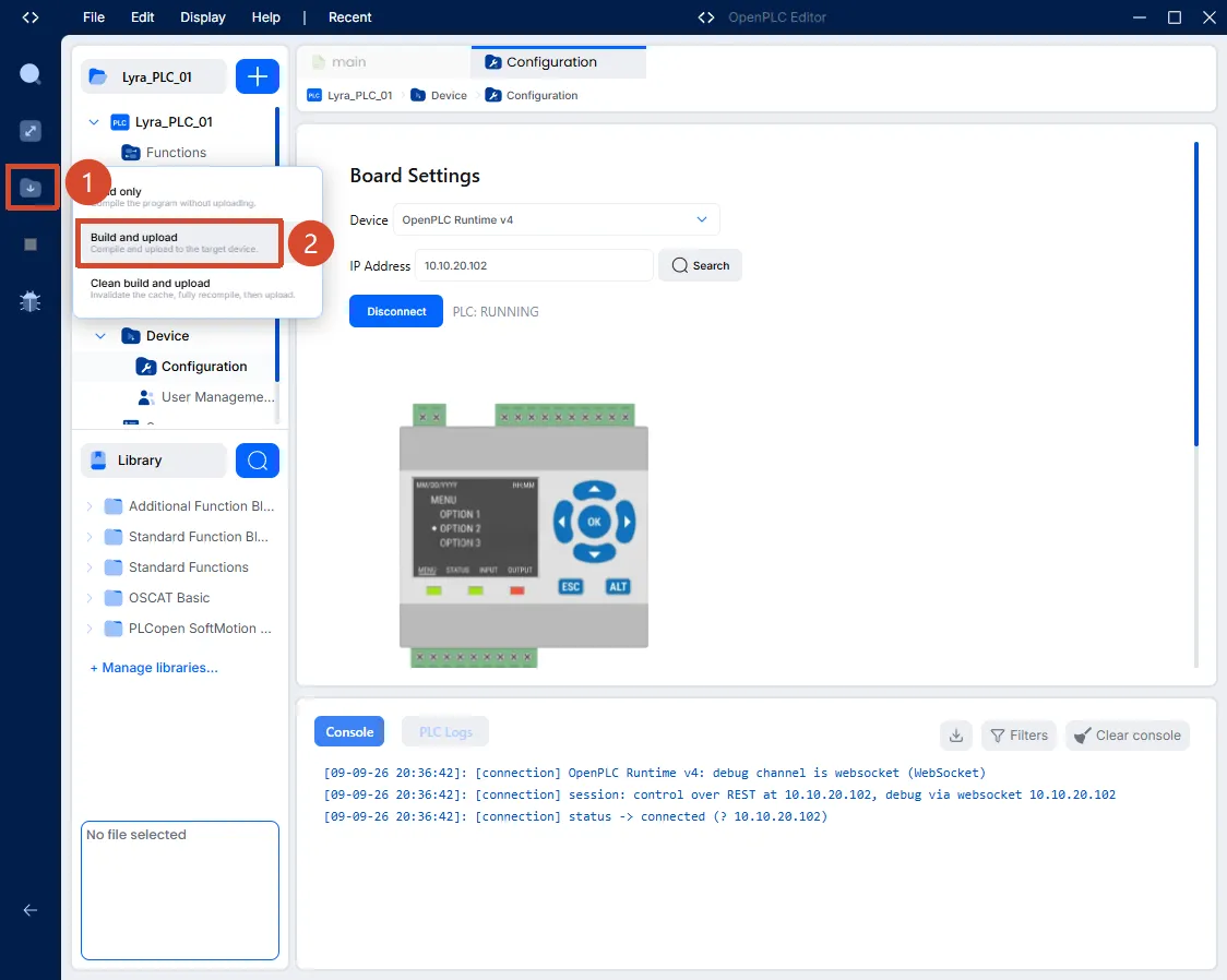
Click the build icon in the left toolbar.
-
Click "Build and Upload".
-
Wait for the console to report that the build, upload, and startup completed successfully.
-
When the program starts, onboard relay 0 should energize once. Confirm the state by listening for the relay or by checking the contacts with a multimeter.
After the test, stop the PLC or set the initial value of AlwaysOn to FALSE and upload the program again to release the relay.