luckfox-config
Luckfox Lyra pins have multiple multiplexing functions. Depending on the needs of the actual project, adjustments to the device tree are often required. This section introduces two methods for configuring Luckfox Lyra pin multiplexing during the compilation and system runtime stages, allowing flexible configuration of Luckfox Lyra pin interface functions.
1. luckfox-config Overview
luckfox-config is a tool in the Luckfox Lyra root file system that allows for quick configuration of device functions on Luckfox Lyra By using the dynamic device tree mechanism and the fdt tool, most device configurations can be completed without recompiling the dtb.
Terminal Support
System Type Buildroot Serial Port Supported SSH Supported ADB The arrow keys on the keyboard are not functioning. Functionality
System Type Buildroot PWM Supported UART Supported I2C Supported SPI Supported CAN Supported MIPI DSI Supported
2. luckfox-config Configuration
Note: The configuration of luckfox-config is based on the default device tree file. If the device tree has been adjusted during image compilation, some functions may not work properly.
2.1 Structure
luckfox-configluckfox-config dynamic device tree configuration tool, can perform graphical interactive configuration/etc/luckfox.cfgstores configuration information, which users can edit. The configuration items are loaded each time the root filesystem startsluckfox-config Pin diagramis used to temporarily store key information about the system configuration, allowing users to intuitively understand the current pin configuration status.
2.2 Basic Usage
Run the following command in the development board terminal to open the graphical configuration interface:
luckfox-config- Effect Preview:
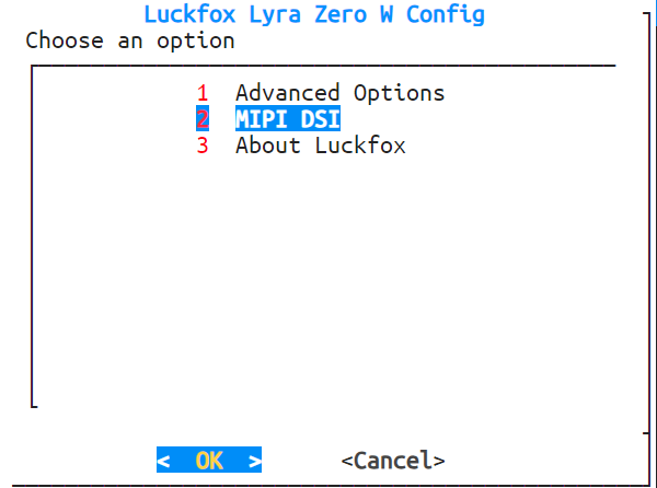
- Effect Preview:
Use the ↑ and ↓ keys to select menu items, the enter key to enter, and the ←, → keys or Tab to select the OK and cancel buttons. Use the Esc key to cancel and return, and the space bar to select an option. Any changes will take effect after restarting. Note: When logging in via ADB, you cannot use the direction keys or Tab. Instead, use numbers to select options and enter to confirm.
View the configuration status. When a pin is enabled, it will be marked with an "*" and locked. If the newly enabled interface contains locked pins, it cannot proceed. You can view the current pin lock status in the about menu of luckfox-config or by using the following command:
luckfox-config show- If the pin reuse function is not specified in the pin diagram, the corresponding GPIO will be directly marked.
Save the configuration
Common pin reuse configurations (e.g., PWM, UART, I2C, SPI) take effect immediately. Devices whose drivers do not support dynamic detection (e.g., DSI) need a reboot to take effect.
Note: Settings that need a reboot to take effect are made by directly modifying the dtb. The ENABLE status in luckfox.cfg is only for record. Simply modifying luckfox.cfg does not take effect during configuration loading.
Load the configuration:
luckfox-config load*Note:** Settings that need a reboot to take effect are made by directly modifying the dtb. The ENABLE status in luckfox.cfg is only for record. Simply modifying luckfox.cfg does not take effect during configuration loading.
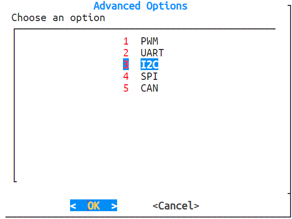
3 Common Configurations
3.1 PWM Configuration
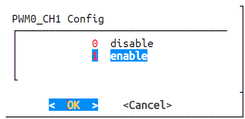
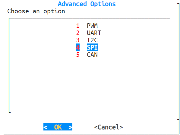
Enter the Advanced Options -> PWM interface, and luckfox-config will display all supported PWM configurations.
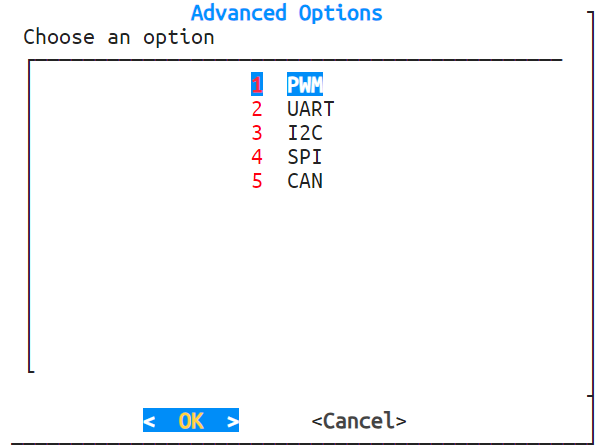
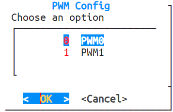
Use the arrow keys to select the PWM channel you wish to configure.
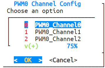
In the configuration menu, you can perform the following actions:
- Select enable to activate the PWM channel;
- Select disable to deactivate the channel;
- Select Cancel to return to the previous menu without making changes.
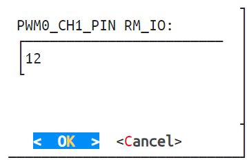
You can further specify a particular pin (e.g., RMIO12) as the PWM output. The system will bind the selected pin accordingly.
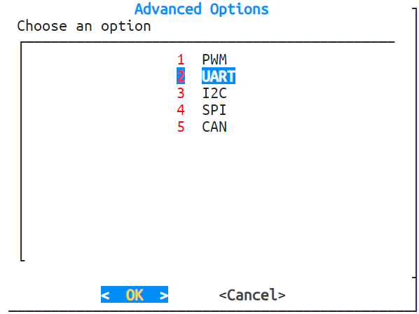
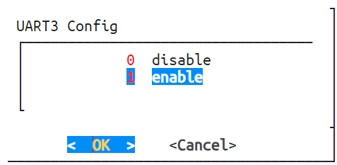
3.2 UART Configuration
Navigate to Advanced Options -> UART. The luckfox-config tool will display all supported UART configuration options.
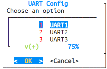
In the configuration menu, you can perform the following actions:
- Select enable to activate UART3;
- Select disable to deactivate this channel;
- Select Cancel to return to the previous menu without making changes.
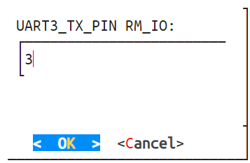
You can further assign specific pins, such as RMIO3 and RMIO4, as the TX and RX pins for UART3. The system will bind the pins accordingly based on your selection.

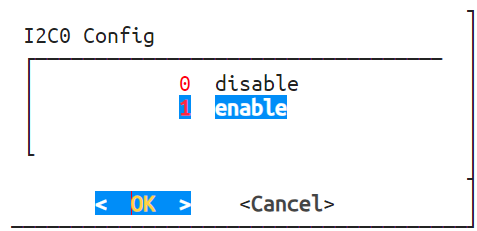
3.3 I2C Configuration
Navigate to Advanced Options -> I2C. The luckfox-config tool will display all supported I2C configuration options.
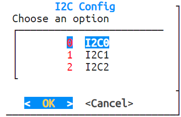
In the configuration menu, you can perform the following actions:
- Select enable to activate I2C0;
- Select disable to deactivate this channel;
- Select Cancel to return to the previous menu without making changes.
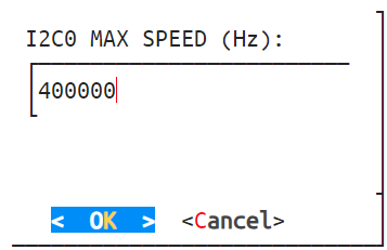
You can further assign specific pins, such as RMIO7 and RMIO8, as the SDA and SCL pins for I2C0. The system will bind the pins accordingly.


Set the I2C bus speed.
3.4 SPI Configuration
Navigate to Advanced Options -> SPI. The luckfox-config tool will display all supported SPI configuration options.
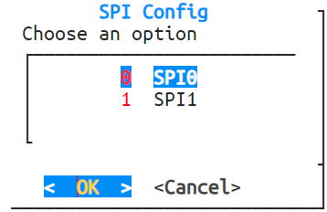
In the configuration menu, you can perform the following actions:
- Select enable to activate SPI0;
- Select disable to deactivate this channel;
- Select Cancel to return to the previous menu without making changes.
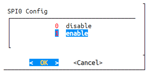
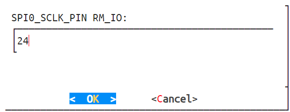
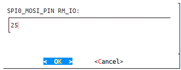
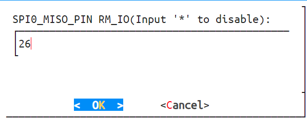
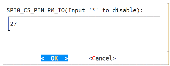
You can further assign specific pins, such as RMIO24, RMIO25, RMIO26, and RMIO27, as the CLK, MOSI, MISO, and CS pins for SPI0. The system will bind the pins accordingly.
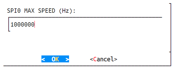
Set the SPI bus speed.
3.5 CAN Configuration
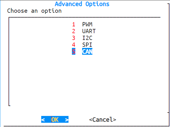
Navigate to Advanced Options -> CAN. The luckfox-config tool will display all supported CAN configuration options.
In the configuration menu, you can perform the following actions:
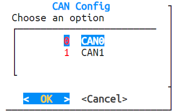
- Select enable to activate CAN0;
- Select disable to deactivate this channel;
- Select Cancel to return to the previous menu without making changes.
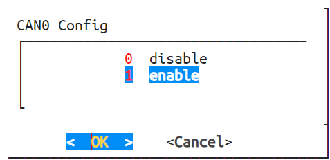
You can further assign specific pins, such as RMIO10 and RMIO11, as the TX and RX pins for CAN0. The system will bind the pins accordingly.

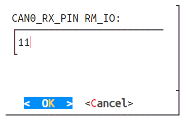
Set the CAN bus speed.
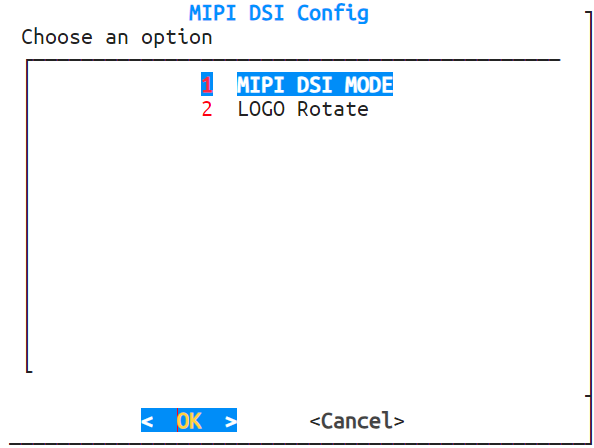
3.6 DSI Configuration
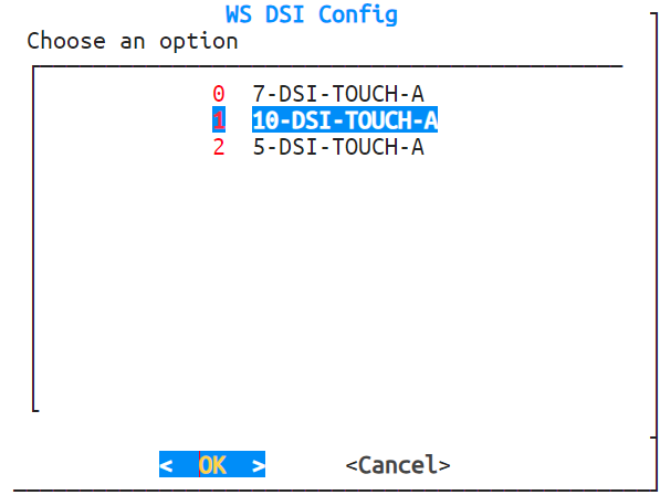
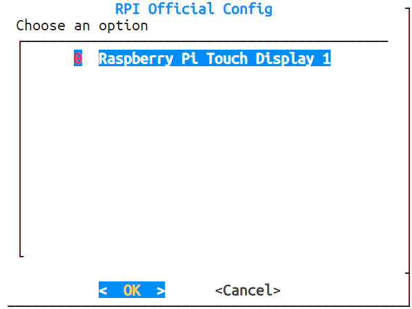
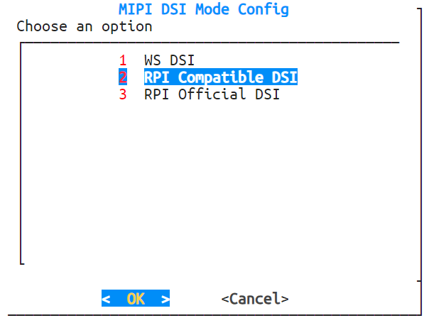
Navigate to MIPI DSI -> MIPI DSI MODE. The luckfox-config tool will display all supported screen configurations.
- 5/7/10.1-inch DSI-TOUCH-A displays:
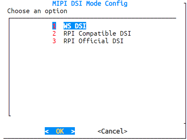
- Official Raspberry Pi DSI display (800×480 resolution):
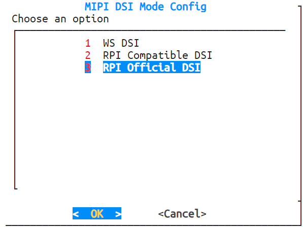
- Compatible displays from Waveshare:
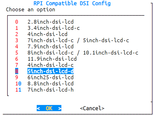
- 5/7/10.1-inch DSI-TOUCH-A displays: