FAQ
Whether you're a beginner or an experienced developer, you may encounter questions or challenges when using the development board. This FAQ aims to provide answers to common questions about the Luckfox Pico series development boards, helping you develop and experiment more smoothly.
1. MASKROM Device Not Recognized
Some users may find that SocToolKit cannot detect the USB device when they first receive the board. We understand that you might worry about potential damage during shipping, but please note: all devices undergo strict quality control before leaving the factory, and the failure rate during shipping is extremely low. In most cases, this issue is related to the user’s computer environment, operating system, USB port, or cable selection. We recommend troubleshooting the following aspects:
Check Whether the Driver Is Installed Successfully
Ensure that you have correctly installed the official DriverAssistant from Rockchip. We recommend using Windows 10 or Windows 11 for better compatibility and stability.Temporarily Disable Antivirus Software When Downloading or Running the Flash Tool
Some antivirus software may falsely flag or quarantine key configuration files in the flash tool, preventing SocToolKit from recognizing the device. Please disable your antivirus temporarily before downloading or using the tool.Use a High-Quality USB Type-C Data Cable (Very Important!)
Be sure to use a reliable USB Type-C cable that supports data transfer.We’ve found that many users switch between multiple cables, yet the issue persists—usually due to poor cable quality.
Merely using "many" cables doesn’t help; quantity doesn’t equal quality. It’s highly recommended to use the original cable included with the board or a branded high-speed data cable to ensure stable connection and data transmission.
Low-cost cables may support only charging, not data communication.Check If the USB Port Is Occupied by Other Programs
Programs like virtual machines or mobile management software might occupy USB resources and cause conflicts. Try closing such software and retrying.Use Rear USB Ports on Desktop PCs
Front USB ports are often extended via internal wiring, which may result in insufficient power delivery. This can affect the detection and flashing of high-power devices. It’s recommended to use the rear ports directly connected to the motherboard.Avoid Using USB Hubs
Although less common, some USB hubs have compatibility issues that may cause flashing failures or unrecognized devices. Always connect the device directly to the PC's built-in USB port.
2. Flashing Failure
- SocToolKit recognizes the MASKROM device, but fails at DownloadBin...
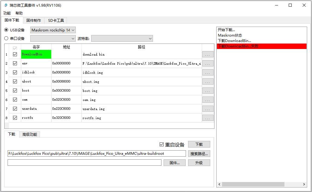
- Answer: The most likely cause is still the USB cable. Please replace it with a high-quality Type-C data cable.
- SocToolKit recognizes the MASKROM device, but fails at env... download.

- Answer: When using a virtual machine, the host may re-access the USB interface during flashing, prompting a confirmation window. If you don’t click "OK", the flashing process will fail.
- Also: Avoid using a USB hub. Connect the USB cable directly to your computer.
3. UART / Serial Communication Issues
The development board uses an onboard USB-to-TTL interface for debugging. Therefore, the serial adapter used must support TTL-level signals.If you experience garbled output during serial debugging, please follow this troubleshooting order:
- Ensure the serial module type is correct (must be USB to TTL).
- Verify the serial software settings (baud rate, data bits, stop bits, etc.) match the board's configuration.
- Double-check serial wiring (TX ↔ RX, and GND connected).
- Try another serial adapter:If all settings and connections are correct and the problem persists, your current serial module may have compatibility issues or hardware faults. Try using another adapter to confirm.
In most cases, the development board’s serial hardware is stable and reliable; issues are more likely caused by the serial adapter or its connection.
4. Memory and Storage Allocation
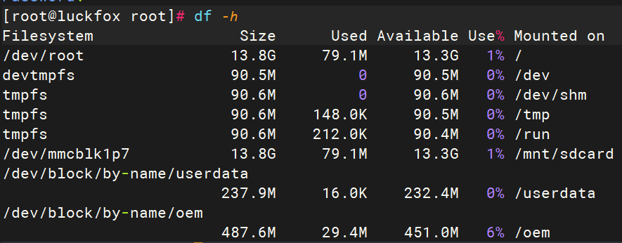
After logging into the development board, users often check device resources such as available memory and storage space. Some observant users may notice that the actual values differ from those listed on the official website. The following analysis is based on debug serial port logs:
Memory Allocation (Example: Luckfox Pro Max)
[ 0.000000] Memory: 185364K/262144K available (3879K kernel code, 390K rwdata, 1884K rodata, 200K init, 139K bss, 9196K reserved, 67584K cma-reserved)Total memory: 262144K = 262144 ÷ 1024 = 256 MB
Available memory: 185364K = 185364 ÷ 1024 = 181 MB
Reserved memory: 9196K is reserved and not accessible by user space
CMA-reserved (Contiguous Memory Allocator): 67584K = about 24 MB, specifically reserved for the camera
Storage Space
 [    0.083327] spi-nand spi2.0: Winbond SPI NAND was found.
 [    0.083357] spi-nand spi2.0: 256 MiB, block size: 128 KiB, page size: 2048, OOB size: 128
 [    0.084362] 7 cmdlinepart partitions found on MTD device spi-nand0
 [    0.084377] Creating 7 MTD partitions on "spi-nand0":
 [    0.084391] 0x000000000000-0x000000040000 : "env"
 [    0.086046] 0x000000040000-0x000000080000 : "idblock"
 [    0.087560] 0x000000080000-0x000000100000 : "uboot"
 [    0.089060] 0x000000100000-0x000000500000 : "boot"
 [    0.090585] 0x000000500000-0x000002300000 : "oem"
 [    0.092290] 0x000002300000-0x000002d00000 : "userdata"
 [    0.093907] 0x000002d00000-0x00000ff00000 : "rootfs"
This shows that the SPI NAND Flash has a total capacity of 256 MiB.
Partition size breakdown:
Partition Start Address End Address Size (Hex) Size (Bytes) Size (Readable) env0x000000000000 0x000000040000 0x40000 262144 Bytes 256 KB idblock0x000000040000 0x000000080000 0x40000 262144 Bytes 256 KB uboot0x000000080000 0x000000100000 0x80000 524288 Bytes 512 KB boot0x000000100000 0x000000500000 0x400000 4194304 Bytes 4 MB oem0x000000500000 0x000002300000 0x1E00000 31457280 Bytes 30 MB userdata0x000002300000 0x000002d00000 0xA00000 10485760 Bytes 10 MB rootfs0x000002d00000 0x00000ff00000 0xC200000 203843584 Bytes ~194.375 MB Root filesystem log:
 [    0.867750] ubi0: scanning is finished
[ 0.872937] ubi0: attached mtd6 (name "rootfs", size 210 MiB)- After mounting, the rootfs size is reported as 210 MiB
Summary:The UBIFS filesystem uses physical erase blocks (PEB) and logical erase blocks (LEB). Space is also reserved for journaling, recovery, and wear-leveling mechanisms.As a result, although the rootfs is reported as 209 MiB (which converts to ~219.15 MB using 1 MiB = 1.048576 MB), the actual usable space will be slightly smaller, approximately 190 MB after subtracting system overhead.
5. Memory Reallocation
As described in the Memory and Storage Allocation section, each partition's size and usage can be flexibly adjusted within the SDK to meet different needs. Once changes are made, recompile the image to apply the modifications.
Runtime Memory Allocation (Pico Series):
Model Total RAM Reserved for Camera Reserved for Camera Luckfox Pico 64 MB 24 MB ~35 MB Luckfox Pico Mini A/B 64 MB 24 MB ~35 MB Luckfox Pico Plus 64 MB 24 MB ~35 MB Luckfox Pico Pro 128 MB 66 MB ~60 MB Luckfox Pico Max 256 MB 66 MB ~190 MB Luckfox Pico Ultra B/ BW 128 MB 66 MB ~60 MB Luckfox Pico Ultra/Ultra W 256 MB 66 MB ~190 MB Luckfox Pico Pi A 256 MB 66 MB ~190 MB Luckfox Pico Pi B 128 MB 66 MB ~60 MB Memory configuration is located in:
luckfox-pico/project/cfg/BoardConfig_IPC/.mk.For details, refer to the “SDK Configuration File Explanation” in the SDK Environment Setup chapter.If the camera is not needed, you can reduce the reserved memory from the default 66MB to 1MB to free up more runtime memory. After modifying the file, recompile the image for the change to take effect.
6. Camera Not Working
- Use the Latest Image: Ensure you have flashed the latest Buildroot image from the official cloud storage.
- Check Camera Wiring: Verify that the MIPI or other interface between the camera and the development board is connected correctly and securely, with the proper pin alignment.
- Same Local Network: Make sure the PC and the development board are on the same local network. Confirm that the PC can successfully ping the board and access it via SSH (required for video streaming later).
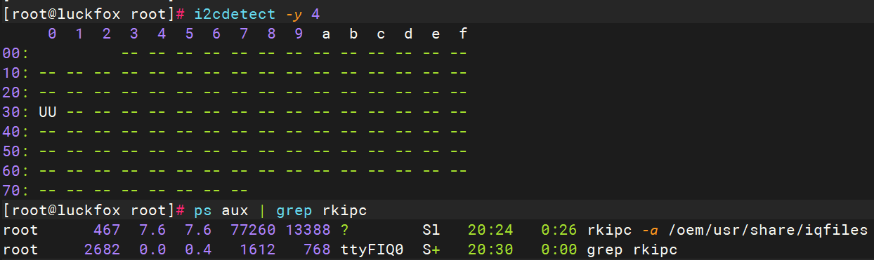
- I2C Detection: Run i2cdetect -y 4 to check if the I2C address of the camera is detected, confirming proper hardware connection.
- Verify CSI Camera Driver Functionality: After enabling CSI, confirm that the rkipc process is running and the camera device is detected under /userdata.
7. System Size and TF Card Capacity
7.1 Mismatch Between System Size and TF Card Capacity
By default, when flashing the official Buildroot image (downloaded from the cloud) onto a TF card, even if the card has a capacity of 16GB, the system might only show ~8GB of usable space. This happens because the image does not automatically resize partitions based on the TF card's actual capacity. The partition sizes are fixed in the SDK build configuration, which defaults to 8GB. To fully utilize the TF card space, you have two options:
Method 1: Modify SDK Partition Size (Recommended if you can rebuild the image)
- Navigate to the board configuration file:
luckfox-pico/project/cfg/BoardConfig_IPC/.mk - Modify the rootfs partition size according to your needs. For most applications, adjusting the rootfs size is sufficient.
- Rebuild the image and flash it to the TF card. For detailed parameter explanation, see SDK Environment Setup → SDK Configuration File Explanation.
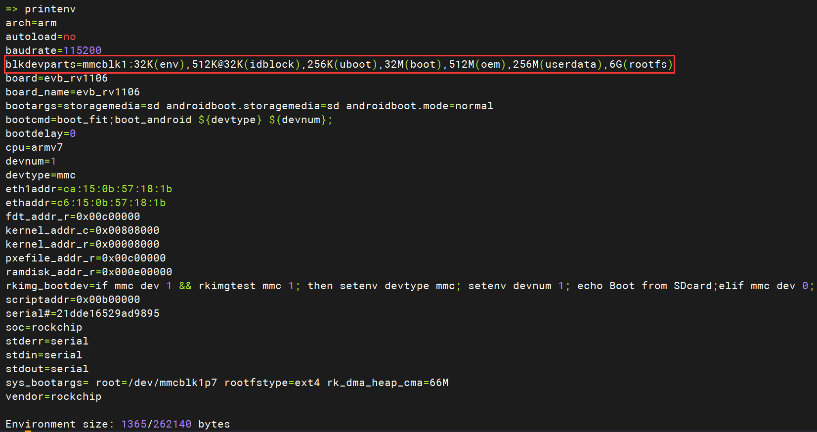
Method 2: Modify Partition Layout via U-Boot (For already-built images)
Connect the board to your PC via UART and reboot the board.
During boot, press Ctrl + C to interrupt and enter U-Boot command line:
=>Run the following commands to expand the rootfs partition to use all remaining space on the TF card (other partitions remain unchanged):
setenv blkdevparts 'mmcblk1:32K(env),512K@32K(idblock),256K(uboot),32M(boot),512M(oem),256M(userdata),-(rootfs)'
saveenv
reset- Demonstration:
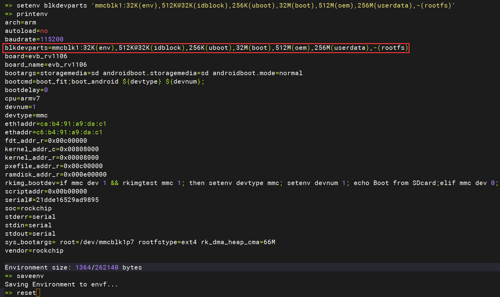
- Demonstration:
7.2 Why is a TF Card with More Than 8GB Required?
The image file is only a few hundred megabytes—why do I need a multi-gigabyte TF card?
- Although the image itself is only a few hundred MB, after booting, the system will automatically resize the partitions (via scripts) according to the settings in the SDK to ensure there’s enough space for stable operation.
- To maintain system stability and allow room for future software installation, log storage, and other needs, it is recommended to use a TF card with at least 8GB of capacity.
8. USB Device Not Recognized
Applicable Models: Luckfox Pico Ultra series and Pico Pi series, which feature a standard USB-A port supporting external USB devices. Please ensure the following configurations are correct:
- Luckfox Pico Pi: Latest system image from the official cloud storage has been flashed.USB device is not recognized (lsusb does not show the device).
- The hardware DIP switch is set to the correct position (Host mode).
- The software setting has been switched to Host mode via luckfox-config.
- Luckfox Pico Ultra: Latest system image from the cloud has been flashed.USB device is not recognized (lsusb output is missing the device).
- Host mode is enabled via luckfox-config.
- Due to limited board resources and space, USB-A and USB-C cannot be used simultaneously.Do not use Type-C for power input. Instead, use PoE or GPIO for power supply.
9. Alternative Power Supply Methods (Besides USB-C)
Luckfox Pico/Pico Mini/Pico Plus/Pico Pro/Pico Max
- VBUS: Connected to the USB Type-C power input. Recommended as the primary power source.
- VSYS: Main system power input, can be used as an alternative power path.
- Both VBUS and VSYS support a voltage range of 4.5V to 5.5V. A stable power supply is recommended, preferably through VBUS.
For Luckfox Pico Ultra series:Support for GPIO or PoE power supply.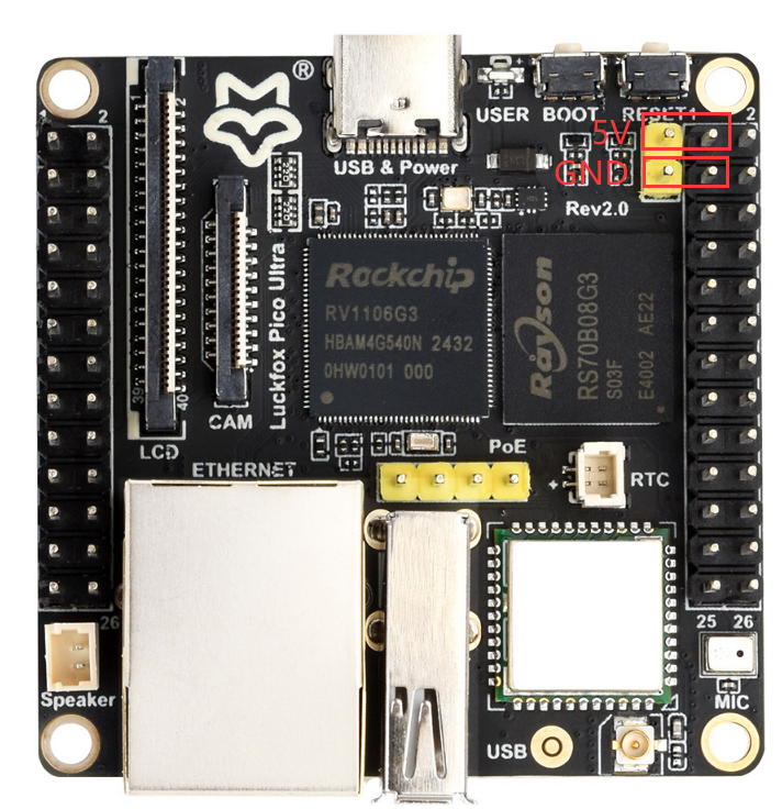
10. Incorrect RGB Screen Resolution Display
Re-flash the latest system image from the cloud storage according to the official guide.The default resolution is 720x720.If your screen is 480x480, wait for the system to fully boot, then press the boot button once to switch resolution.
Use the modetest tool to test different resolutions.See theRGB Screen - section 10.2 DRM Testingfor more details.
modetest -M rockchip -s 70@66:480x480
modetest -M rockchip -s 70@66:720x720
11. How to Change the Boot Logo for Luckfox Pico Ultra Series
To change the boot logo, simply replace the following file and rebuild the kernel image:luckfox-Pico/sysdrv/source/kernel/drivers/video/logo/logo_linux_clut224.ppmConvert Your Image to .ppm Format:
# Install the required tool
sudo apt-get install netpbm

# Convert PNG (or other formats) to .ppm
pngtopnm <你的png图片 >./LOGO.pnm # For other formats, use jpegtopnm or bmptopnm
pnmquant 224 ./LOGO.pnm >./LOGO224.pnm
pnmtoplainpnm ./LOGO224.pnm >LOGO.ppm