PWM
1. Introduction to PWM
PWM, or Pulse Width Modulation, is a technique used to generate analog signal output by controlling the pulse width of a digital signal. It is commonly employed in embedded systems and electronic devices for applications such as motor speed control, LED brightness adjustment, and audio signal generation. In Linux systems, PWM devices are typically managed and configured via the sysfs filesystem, with the device directories usually located under /sys/class/pwm/.
2. Controlling PWM (Shell)
2.1 Pin Distribution
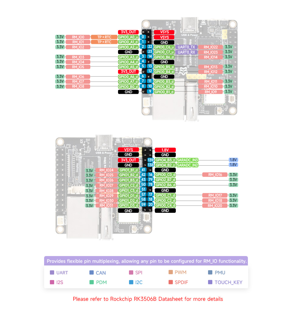
- Luckfox Lyra Ultra/Ultra W Pin Diagram:
2.2 Device Directory and Attributes
Check the PWM interface, pwmchip0 (note: pwmchip0 is ff932000 at this time) is the backlight of the screen, which is enabled by default:
root@luckfox:~# ls -l /sys/class/pwm
total 0
lrwxrwxrwx    1 root     root  0 Jan  1 00:00 pwmchip0 -> ../../devices/platform/ff932000.pwm/pwm/pwmchip0
When multiple PWM device tree overlays are enabled, the system assigns smaller
pwmchipnumbers to PWM controllers with smaller values.The
/sys/class/pwm/pwmchipN/pwm0/directory contains multiple attributes that can be configured to control the PWM.root@luckfox:/# ls /sys/class/pwm/pwmchip0/pwm0/
capture duty_cycle enable period polarity power ueventenable: Enables or disables the PWM channelperiod: Sets the PWM signal periodduty_cycle: Sets the PWM signal duty cyclepolarity: Configures PWM signal polaritypower/control: Manages power settings for power-saving modes
2.3 Controlling PWM
Export or Unexport PWM to/from User Space.
echo 0 > /sys/class/pwm/pwmchip0/export
echo 0 > /sys/class/pwm/pwmchip0/unexport
Set the PWM period unit to ns. For example, the period of a 1KHz frequency is 1000000ns (note that in any case, the value of period must be greater than or equal to the value of duty_cycle).
echo 1000000 > /sys/class/pwm/pwmchip10/pwm0/periodSet PWM polarity normal or inverted.
echo "normal" > /sys/class/pwm/pwmchip0/pwm0/polarity
echo "inversed" > /sys/class/pwm/pwmchip0/pwm0/polarity
Enable and disable PWM.
echo 1 > /sys/class/pwm/pwmchip1/pwm0/enable
echo 0 > /sys/class/pwm/pwmchip1/pwm0/enable
Set the duty cycle (less than or equal to period )
echo 100000 > /sys/class/pwm/pwmchip0/pwm0/duty_cycle
echo 200000 > /sys/class/pwm/pwmchip0/pwm0/duty_cycle
echo 300000 > /sys/class/pwm/pwmchip0/pwm0/duty_cycle
echo 400000 > /sys/class/pwm/pwmchip0/pwm0/duty_cycle
echo 500000 > /sys/class/pwm/pwmchip0/pwm0/duty_cycle
echo 600000 > /sys/class/pwm/pwmchip0/pwm0/duty_cycle
echo 700000 > /sys/class/pwm/pwmchip0/pwm0/duty_cycle
echo 800000 > /sys/class/pwm/pwmchip0/pwm0/duty_cycle
echo 900000 > /sys/class/pwm/pwmchip0/pwm0/duty_cycle
echo 1000000 > /sys/class/pwm/pwmchip0/pwm0/duty_cycle
echo 0 > /sys/class/pwm/pwmchip0/pwm0/duty_cycle
3. Controlling PWM Using Python (python-periphery)
The complete example code for PWM output using the python-periphery library is as follows:
#!/usr/bin/python3

from periphery import PWM
import time

pwm = PWM(1, 0)

try:
    pwm.frequency = 1000
    pwm.duty_cycle = 0
    pwm.polarity = "normal"
    pwm.enable()

    direction = 1

    while True:
        pwm.duty_cycle += 0.01 * direction
        pwm.duty_cycle = round(pwm.duty_cycle, 2)
        if pwm.duty_cycle == 1.0:
            direction = -1
        elif pwm.duty_cycle == 0.0:
            direction = 1

        time.sleep(0.05)

except KeyboardInterrupt:
    pass

finally:
    pwm.close()
Program analysis.
pwm = PWM(1, 0)         # Enable PWM chip 0, channel 0
pwm.frequency = 1000    # Set 1000Hz frequency
pwm.polarity = "normal" # Set PWM polarity
pwm.duty_cycle = 0      # Initial duty cycle
pwm.enable() # Enable PWM- This code snippet implements a simple PWM output. The duty cycle of PWM is adjusted continuously through a loop to achieve the breathing light effect.
pwm.duty_cycleincreases by 0.01 each time (can be adjusted as needed), and uses theroundfunction to keep it to two decimal places. When the maximum or minimum value is reached, the direction is reversed. And after each update of the PWM value, the speed of the breathing light is controlled bytime.sleep.
while True:
    pwm.duty_cycle += 0.01 * direction
    pwm.duty_cycle = round(pwm.duty_cycle, 2)
    if pwm.duty_cycle == 1.0:
        direction = -1
    elif pwm.duty_cycle == 0.0:
        direction = 1

    print(pwm.duty_cycle)
time.sleep(0.05)- This code snippet implements a simple PWM output. The duty cycle of PWM is adjusted continuously through a loop to achieve the breathing light effect.
Run the Script:
chmod +x pwm.py
./pwm.py
Observe the output on Pin 12 (breathing light).

4. Control PWM (C program)
In addition to controlling the PWM pins through shell scripts and Python libraries, you can also use C language to operate sysfs to achieve the same function.
导出用户空间。
int pwm_export(int channel) {
    FILE *pwm_export = fopen(PWM_PATH "/export", "w");
    if (!pwm_export) {
        perror("Failed to open PWM export");
        return 1;
    }
    fprintf(pwm_export, "%d", channel);
    fclose(pwm_export);
    return 0;
}
Unexport userspace.
int pwm_unexport(int channel) {
    FILE *pwm_unexport = fopen(PWM_PATH "/unexport", "w");
    if (!pwm_unexport) {
        perror("Failed to open PWM unexport");
        return 1;
    }
    fprintf(pwm_unexport, "%d", channel);
    fclose(pwm_unexport);
    return 0;
}
Set the PWM period.
int pwm_set_period(int channel, int period_ns) {
    char period_path[128];
    snprintf(period_path, sizeof(period_path), PWM_PATH "/pwm%d/period", channel);

    FILE *period_file = fopen(period_path, "w");
    if (!period_file) {
        perror("Failed to open PWM period");
        return 1;
    }
    fprintf(period_file, "%d", period_ns);
    fclose(period_file);
    return 0;
}
Set the duty cycle.
int pwm_set_duty_cycle(int channel, int duty_cycle_ns) {
    char duty_cycle_path[128];
    snprintf(duty_cycle_path, sizeof(duty_cycle_path), PWM_PATH "/pwm%d/duty_cycle", channel);

    FILE *duty_cycle_file = fopen(duty_cycle_path, "w");
    if (!duty_cycle_file) {
        perror("Failed to open PWM duty cycle");
        return 1;
    }
    fprintf(duty_cycle_file, "%d", duty_cycle_ns);
    fclose(duty_cycle_file);
    return 0;
}
Enable PWM.
int pwm_enable(int channel, int enable) {
    char enable_path[128];
    snprintf(enable_path, sizeof(enable_path), PWM_PATH "/pwm%d/enable", channel);

    FILE *enable_file = fopen(enable_path, "w");
    if (!enable_file) {
        perror("Failed to open PWM enable");
        return 1;
    }
    fprintf(enable_file, "%d", enable);
    fclose(enable_file);
    return 0;
}
Complete example program.
#include <stdio.h>
#include <stdlib.h>
#include <string.h>
#include <unistd.h>
#include <math.h>

#define PWM_PATH "/sys/class/pwm/pwmchip1"
#define PERIOD_NS 1000000
#define MAX_DUTY_CYCLE_NS 1000000
#define MIN_DUTY_CYCLE_NS 0

#define PI 3.141592653589793


int pwm_export(int channel) {
    FILE *pwm_export = fopen(PWM_PATH "/export", "w");
    if (!pwm_export) {
        perror("Failed to open PWM export");
        return 1;
    }
    fprintf(pwm_export, "%d", channel);
    fclose(pwm_export);
    return 0;
}


int pwm_unexport(int channel) {
    FILE *pwm_unexport = fopen(PWM_PATH "/unexport", "w");
    if (!pwm_unexport) {
        perror("Failed to open PWM unexport");
        return 1;
    }
    fprintf(pwm_unexport, "%d", channel);
    fclose(pwm_unexport);
    return 0;
}


int pwm_set_period(int channel, int period_ns) {
    char period_path[128];
    snprintf(period_path, sizeof(period_path), PWM_PATH "/pwm%d/period", channel);

    FILE *period_file = fopen(period_path, "w");
    if (!period_file) {
        perror("Failed to open PWM period");
        return 1;
    }
    fprintf(period_file, "%d", period_ns);
    fclose(period_file);
    return 0;
}


int pwm_set_duty_cycle(int channel, int duty_cycle_ns) {
    char duty_cycle_path[128];
    snprintf(duty_cycle_path, sizeof(duty_cycle_path), PWM_PATH "/pwm%d/duty_cycle", channel);

    FILE *duty_cycle_file = fopen(duty_cycle_path, "w");
    if (!duty_cycle_file) {
        perror("Failed to open PWM duty cycle");
        return 1;
    }
    fprintf(duty_cycle_file, "%d", duty_cycle_ns);
    fclose(duty_cycle_file);
    return 0;
}


int pwm_enable(int channel, int enable) {
    char enable_path[128];
    snprintf(enable_path, sizeof(enable_path), PWM_PATH "/pwm%d/enable", channel);

    FILE *enable_file = fopen(enable_path, "w");
    if (!enable_file) {
        perror("Failed to open PWM enable");
        return 1;
    }
    fprintf(enable_file, "%d", enable);
    fclose(enable_file);
    return 0;
}

int main() {
    int channel = 0;


    if (pwm_export(channel)) {
        return 1;
    }


    if (pwm_set_period(channel, PERIOD_NS)) {
        return 1;
    }


    if (pwm_enable(channel, 1)) {
        return 1;
    }


    double step_size = (2 * PI) / 100.0;
    while (1) {
        for (double i = 0; i <= 2 * PI; i += step_size) {

            double duty_cycle_ratio = (sin(i) + 1) / 2;
            int duty_cycle_ns = (int)(duty_cycle_ratio * MAX_DUTY_CYCLE_NS);


            if (pwm_set_duty_cycle(channel, duty_cycle_ns)) {
                return 1;
            }

            usleep(20000);
        }
    }


    if (pwm_enable(channel, 0)) {
        return 1;
    }


    if (pwm_unexport(channel)) {
        return 1;
    }

    return 0;
}
Cross-compile and run the program. To build a cross-compilation environment, please refer to the "Program Compilation" or "GPIO" section.
arm-none-linux-gnueabihf-gcc pwm.c -o pwm -lm
5. Device Tree Overview
The device file path is located at
kernel-6.1/arch/arm/boot/dts/rk3506g-luckfox-lyra.dts, and the code snippet for turning onpwmis as follows:/{
pwm_rockchip_test: pwm-rockchip-test {
compatible = "pwm-rockchip-test";
pwms = <&pwm0_4ch_0 0 25000 0>,
<&pwm0_4ch_1 0 25000 0>,
<&pwm0_4ch_2 0 25000 0>,
<&pwm0_4ch_3 0 25000 0>,
<&pwm1_8ch_0 0 25000 0>,
<&pwm1_8ch_1 0 25000 0>,
<&pwm1_8ch_2 0 25000 0>,
<&pwm1_8ch_3 0 25000 0>,
<&pwm1_8ch_4 0 25000 0>,
<&pwm1_8ch_5 0 25000 0>;
pwm-names = "pwm0_0",
"pwm0_1",
"pwm0_2",
"pwm0_3",
"pwm1_0",
"pwm1_1",
"pwm1_2",
"pwm1_3",
"pwm1_4",
"pwm1_5";
};
};
/***********************PWM********************/
&pwm0_4ch_0 {
status = "okay";
pinctrl-names = "active";
pinctrl-0 = <&rm_io12_pwm0_ch0>;
assigned-clocks = <&cru CLK_PWM0>;
assigned-clock-rates = <100000000>;
};
&pwm0_4ch_1 {
status = "okay";
pinctrl-names = "active";
pinctrl-0 = <&rm_io13_pwm0_ch1>;
assigned-clocks = <&cru CLK_PWM0>;
assigned-clock-rates = <100000000>;
};
&pwm0_4ch_2 {
status = "okay";
pinctrl-names = "active";
pinctrl-0 = <&rm_io9_pwm0_ch2>;
assigned-clocks = <&cru CLK_PWM0>;
assigned-clock-rates = <100000000>;
};
&pwm0_4ch_3 {
status = "okay";
pinctrl-names = "active";
pinctrl-0 = <&rm_io8_pwm0_ch3>;
assigned-clocks = <&cru CLK_PWM0>;
assigned-clock-rates = <100000000>;
};
&pwm1_8ch_0 {
status = "okay";
pinctrl-names = "active";
pinctrl-0 = <&rm_io4_pwm1_ch0>;
assigned-clocks = <&cru CLK_PWM1>;
assigned-clock-rates = <100000000>;
};
&pwm1_8ch_1 {
status = "okay";
pinctrl-names = "active";
pinctrl-0 = <&rm_io3_pwm1_ch1>;
assigned-clocks = <&cru CLK_PWM1>;
assigned-clock-rates = <100000000>;
};
&pwm1_8ch_2 {
status = "okay";
pinctrl-names = "active";
pinctrl-0 = <&rm_io2_pwm1_ch2>;
assigned-clocks = <&cru CLK_PWM1>;
assigned-clock-rates = <100000000>;
};
&pwm1_8ch_3 {
status = "okay";
pinctrl-names = "active";
pinctrl-0 = <&rm_io27_pwm1_ch3>;
assigned-clocks = <&cru CLK_PWM1>;
assigned-clock-rates = <100000000>;
};
&pwm1_8ch_4 {
status = "okay";
pinctrl-names = "active";
pinctrl-0 = <&rm_io26_pwm1_ch4>;
assigned-clocks = <&cru CLK_PWM1>;
assigned-clock-rates = <100000000>;
};
&pwm1_8ch_5 {
status = "okay";
pinctrl-names = "active";
pinctrl-0 = <&rm_io25_pwm1_ch5>;
assigned-clocks = <&cru CLK_PWM1>;
assigned-clock-rates = <100000000>;
};