DSI Screen
1. Introduction
DSI (Display Serial Interface) is a high-speed serial communication interface used between display panels and display controllers, widely used in mobile devices, embedded systems, tablets, and other systems requiring high-performance displays. It is standardized by the MIPI (Mobile Industry Processor Interface) Alliance, designed to reduce the number of pins on devices and optimize power consumption.
2. Compatible Screens
The Luckfox Lyra series development board supports the 10.1-DSI-TOUCH-A by default. In addition, we have adapted official Luckfox, Raspberry Pi, and Waveshare DSI screens to ensure their display and touch functionalities work properly.
2.1 Official Luckfox DSI Screens and Compatible Screens (Resolution: 800 x 480)
| Model | Wiki Address |
|---|---|
| 4.3″ DSI Touchscreen | https://www.luckfox.com/Displays/EN-4.3inch-DSI-Touchscreen |
| 5″ DSI Touchscreen | https://www.luckfox.com/Displays/EN-5inch-DSI-Touchscreen |
| 7″ DSI Touchscreen | https://www.luckfox.com/Displays/EN-7inch-DSI-Touchscreen |
| 8inch DSI LCD | https://www.waveshare.com/8inch-dsi-lcd.htm |
2.2 Waveshare DSI Screens
| Model | Wiki Address |
|---|---|
| 10.1inch DSI LCD (C) | https://www.waveshare.com/wiki/10.1inch_DSI_LCD_(C) |
| 8inch DSI LCD (C) | https://www.waveshare.com/wiki/8inch_DSI_LCD_(C) |
| 7inch DSI LCD (C) | https://www.waveshare.com/wiki/7inch_DSI_LCD_(C) |
| 5inch DSI LCD (C) | https://www.waveshare.com/wiki/5inch_DSI_LCD_(C) |
| 2.8inch DSI LCD | https://www.waveshare.com/wiki/2.8inch_DSI_LCD |
| 4inch DSI LCD | https://www.waveshare.com/wiki/4inch_DSI_LCD |
| 7.9inch DSI LCD | https://www.waveshare.com/wiki/7.9inch_DSI_LCD |
| 8.8inch DSI LCD | https://www.waveshare.com/wiki/8.8inch_DSI_LCD |
| 11.9inch DSI LCD | https://www.waveshare.com/wiki/11.9inch_DSI_LCD |
| 3.4inch DSI LCD (C) | https://www.waveshare.com/wiki/3.4inch_DSI_LCD_(C) |
| 4inch DSI LCD (C) | https://www.waveshare.com/wiki/4inch_DSI_LCD_(C) |
| 5inch DSI LCD (D) | https://www.waveshare.com/wiki/5inch_DSI_LCD_(D) |
| 6.25inch DSI LCD | https://www.waveshare.com/wiki/6.25inch_DSI_LCD |
| 10.1-DSI-TOUCH-A | https://www.waveshare.com/10.1-dsi-touch-a.htm |
3. Hardware Connections
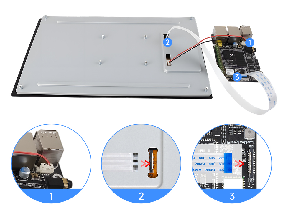
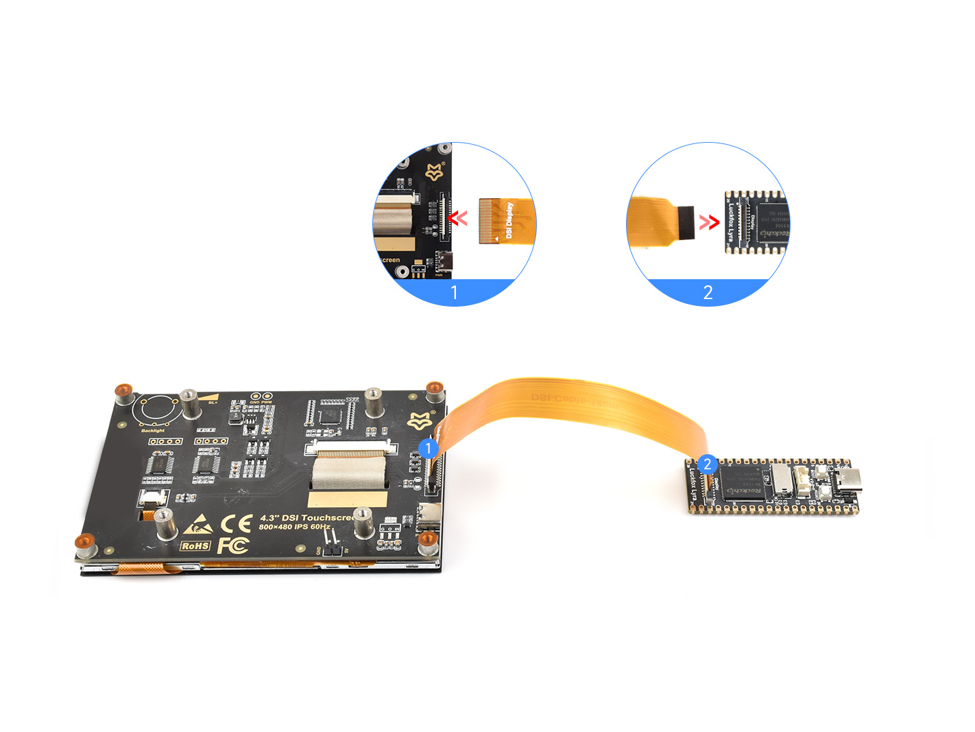
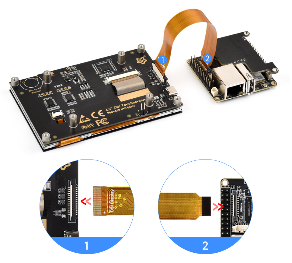
3.1 Luckfox Lyra Connecting to 10.1-DSI-TOUCH-A Screen
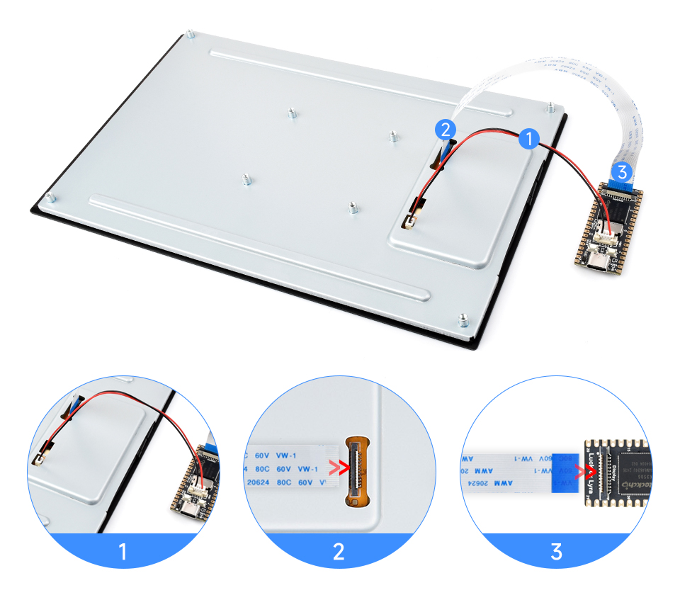
Please ensure the ribbon cable is connected correctly according to your specific development board model. If the screen fails to light up immediately after switching, power off the device immediately and check the wiring to avoid potential damage or other abnormal behavior.
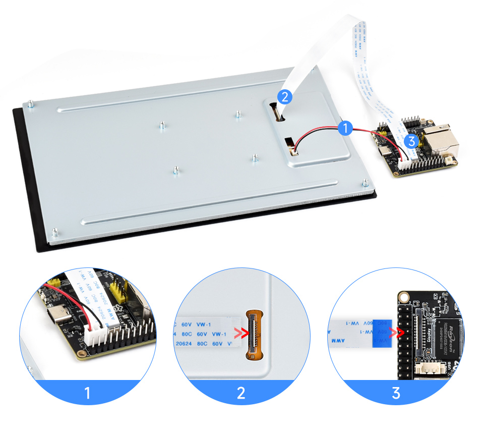
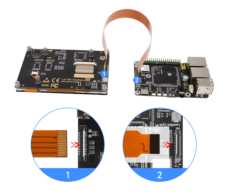
- Use a 22PIN FPC cable to connect the display’s DSI interface to the DSI interface on the Luckfox-Lyra motherboard.
- Use an MX1.25 2PIN to 4PIN connector cable to connect the display’s power interface to the USB MX1.25 4P interface on the Luckfox-Lyra motherboard. As shown below:
- Luckfox Lyra/Lyra Plus:
- Luckfox Lyra Ultra/Ultra W :
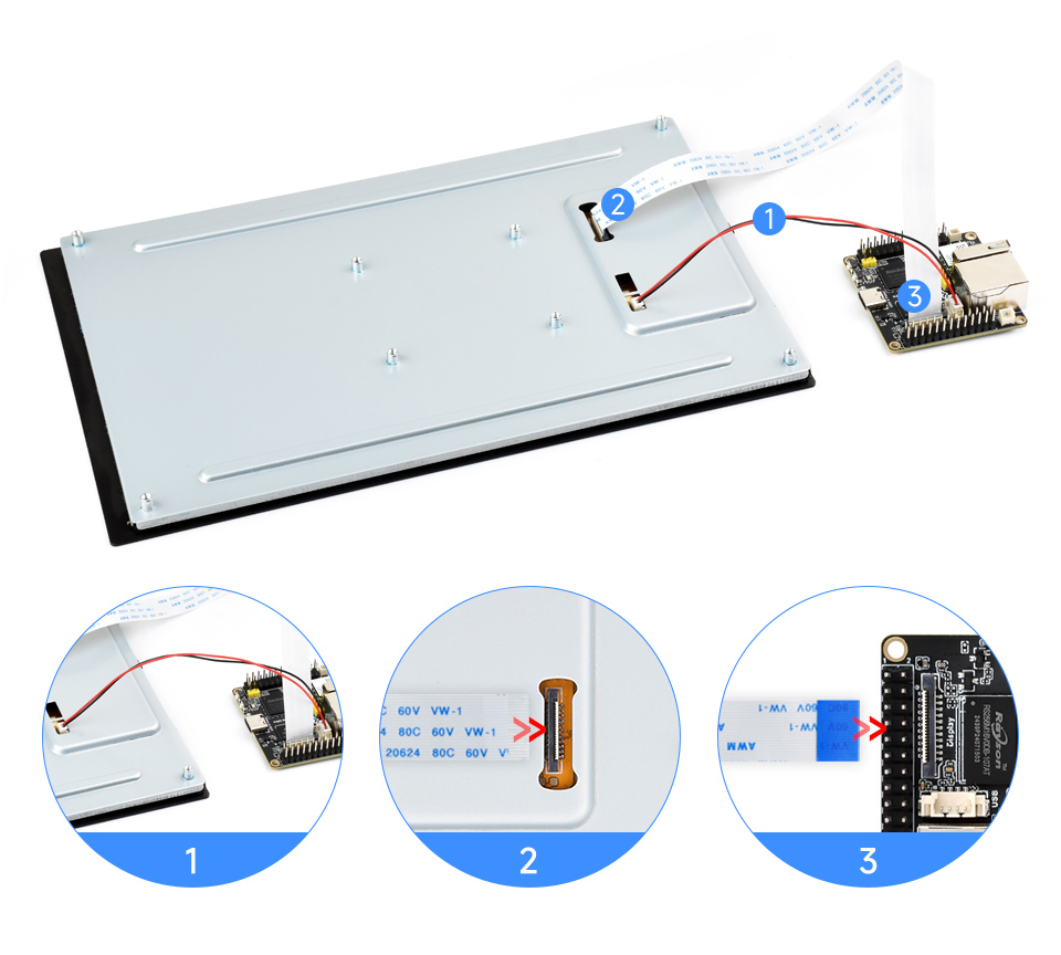
- Luckfox Lyra Zero W:
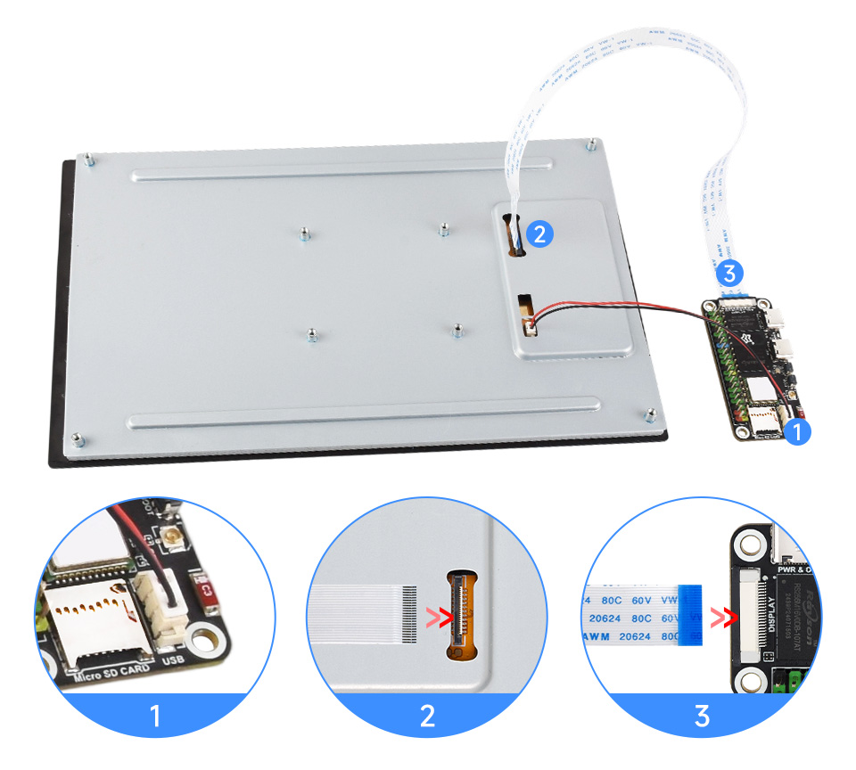
- Luckfox Lyra Pi:
- Luckfox Lyra/Lyra Plus:
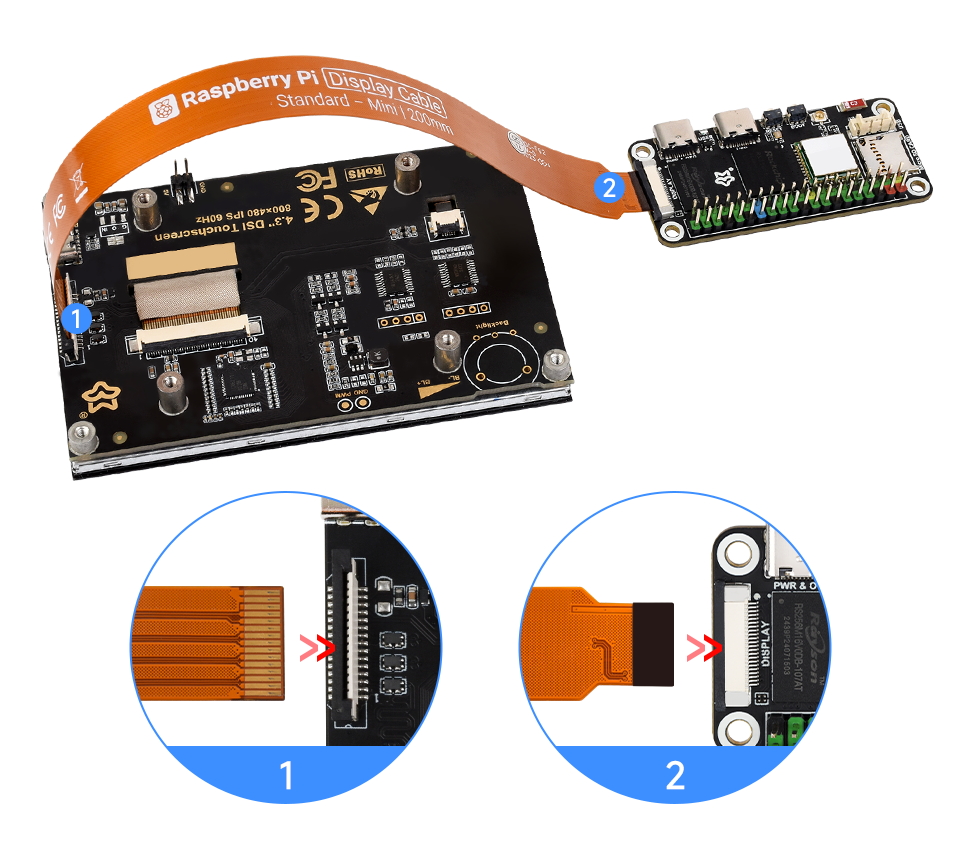
3.2 Luckfox Lyra Connecting to Raspberry Pi DSI Screen
- Use a 15PIN to 22PIN FPC cable Pi5-Display-Cable.
- Luckfox Lyra/Lyra Plus:
- Luckfox Lyra/Lyra Plus:
- Luckfox Lyra Zero W:
- Luckfox Lyra Pi:
- Luckfox Lyra/Lyra Plus:
4. Software Configuration
For individual developers, we provide a more convenient screen switching solution — use the built-in tool luckfox-config on the development board to select the target screen model without manually modifying the device tree. For more details, see:luckfox-config《3.6 DSI配置》
Users may also manually modify the corresponding device tree configuration if needed.as detailed in theSDK Environment Deployment "6. Device tree configuration"
5. Viewing Screen Information
The screen ID available on the current system can be viewed with the following command:
cat /sys/kernel/debug/dri/0/summaryOutput:
VOP [ff600000.vop]: ACTIVE
    Connector: DSI-1
        bus_format[100a]: RGB888_1X24
        overlay_mode[0] output_mode[0]color-encoding[1] color-range[1]
    Display mode: 800x1280p60
        dclk[70000 kHz] real_dclk[69475 kHz] aclk[294912 kHz] type[48] flag[a]
        H: 800 840 860 880
        V: 1280 1310 1314 1324
    win1-0: ACTIVE
        format: XR24 little-endian (0x34325258) SDR[0] color-encoding[0] color-range[0]
        csc: y2r[0] r2r[0] r2y[0] csc mode[0]
        zpos: 0
        src: pos[0x0] rect[800x1280]
        dst: pos[0x0] rect[800x1280]
        buf[0]: addr: 0x06100000 pitch: 3200 offset: 0
    post: sdr2hdr[0] hdr2sdr[0]
    pre : sdr2hdr[0]
    post CSC: r2y[0] y2r[0] CSC mode[2]
6. Display Test
Use modetest on Lyra to perform a color bar test to validate display output:
Vertical Bar Test (Standard mode):
modetest -M rockchip -s 74@71:800x1280Diagonal Bar Test (Enable tile format):
modetest -M rockchip -s 74@71:800x1280 -Ftiles
7. Touch Test
Use the
evtestcommand to test the touchscreen and check the response of the touch input device. Execute the following command:evtestAfter running the command, the terminal will show output similar to the following. Press “0” to start the touchscreen test, and the terminal will print the event values triggered by the touch actions:
No device specified, trying to scan all of /dev/input/event*
Available devices:
/dev/input/event0:      2-005d Goodix Capacitive TouchScreen
Select the device event number [0-0]:
8. Backlight Control
Other compatible screens share the same driver, supporting 0~255 levels of backlight control. The command for backlight control is:
# brightness level:0 ~ 255
echo <brightness level> > /sys/class/backlight/waveshare_bl/brightness