luckfox-config Configuration
Luckfox Pico pins have multiple multiplexing functions. Depending on the needs of the actual project, adjustments to the device tree are often required. This section introduces two methods for configuring Luckfox Pico pin multiplexing during the compilation and system runtime stages, allowing flexible configuration of Luckfox-Pico pin interface functions.
1. luckfox-config Overview
luckfox-config is a tool in the Luckfox Pico root file system that allows for quick configuration of device functions on Luckfox Pico. By using the dynamic device tree mechanism and the fdt tool, most device configurations can be completed without recompiling the dtb.
Terminal Support
System Type Buildroot Serial Port Supported SSH Supported ADB The arrow keys on the keyboard are not functioning. Functionality
System Type Buildroot GPIO Supported PWM Supported UART Supported I2C Supported SPI Supported FBTFT Supported only on Luckfox Pico / Plus / Pro / Max RGB Supported only on Luckfox Pico Ultra / Ultra W TouchScreen Supported only on Luckfox Pico Ultra / Ultra W USB Supported CSI Supported
2. luckfox-config Configuration
Note: The configuration of luckfox-config is based on the default device tree file. If the device tree has been adjusted during image compilation, some functions may not work properly.
2.1 Structure

luckfox-configdynamic device tree configuration tool, can perform graphical interactive configuration/etc/luckfox.cfgstores configuration information, which users can edit. The configuration items are loaded each time the root filesystem startsluckfox-config Pin diagramis used to temporarily store key information about the system configuration, allowing users to intuitively understand the current pin configuration status.
2.2 Basic Usage
Open the graphical configuration interface:
luckfox-config- Effect Preview::
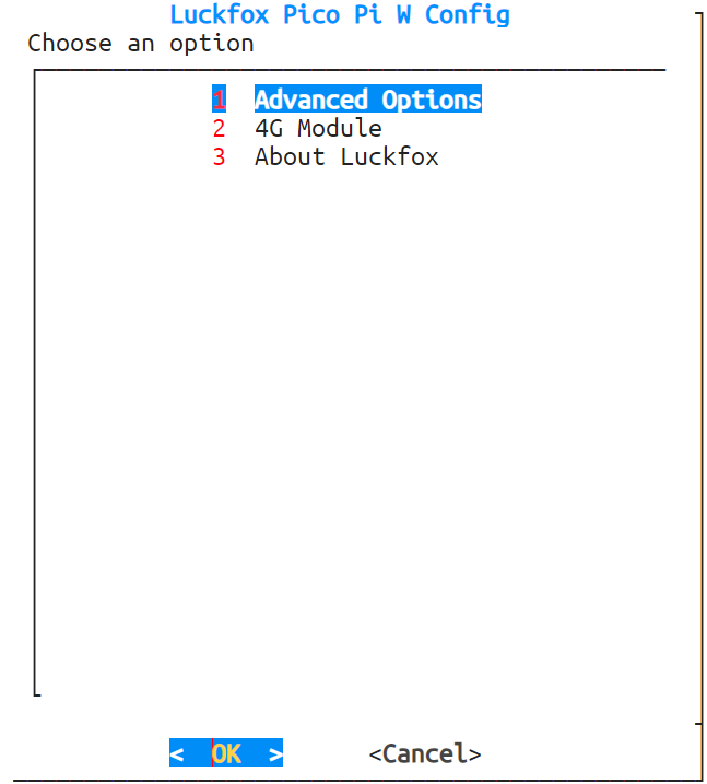
- Effect Preview::
2.Use the ↑ and ↓ keys to select menu items, the enter key to enter, and the ←, → keys or Tab to select the OK and cancel buttons. Use the Esc key to cancel and return, and the space bar to select an option. Any changes will take effect after restarting. Note: When logging in via ADB, you cannot use the direction keys or Tab. Instead, use numbers to select options and enter to confirm.
View the configuration status. When a pin is enabled, it will be marked with an "*" and locked. If the newly enabled interface contains locked pins, it cannot proceed. You can view the current pin lock status in the about menu of luckfox-config or by using the following command:
luckfox-config show- If the pin reuse function is not specified in the pin diagram, the corresponding GPIO will be directly marked.
- In the Luckfox Pico Ultra series, since I2C4 and the CSI camera share pins, the CSI interface is enabled by default, and the pinctrl-0 configuration includes the I2C4 pins, so all I2C4 and RGB pins are marked at the first boot.

Save the configuration
Common pin reuse configurations (e.g., PWM, UART, I2C, SPI) take effect immediately. Devices whose drivers do not support dynamic detection (e.g., FBTFT, RGB, touch screen, CSI) need a reboot to take effect.
Note: Settings that need a reboot to take effect are made by directly modifying the dtb. The ENABLE status in luckfox.cfg is only for record. Simply modifying luckfox.cfg does not take effect during configuration loading.
Load the configuration:
luckfox-config loadNote: Configuration loading is automatically executed during the root filesystem startup phase. A dtboverlay node is created and the configuration is written according to the /etc/luckfox.cfg file. Normally, this command does not need to be executed manually.
2.3 Common Configurations
2.3.1 PWM Configuration
Enter the Advanced Options -> PWM interface, and luckfox-config will display all supported PWM configurations.
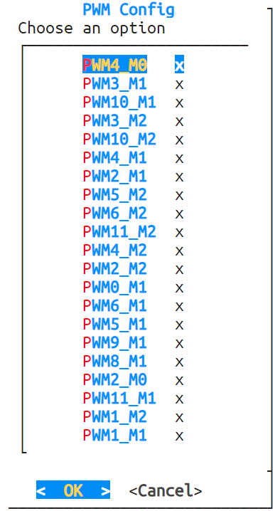
Select the desired option, choose
enableto enable, anddisableto disable. To cancel the configuration, use the direction keys to selectCanceland return to the previous interface.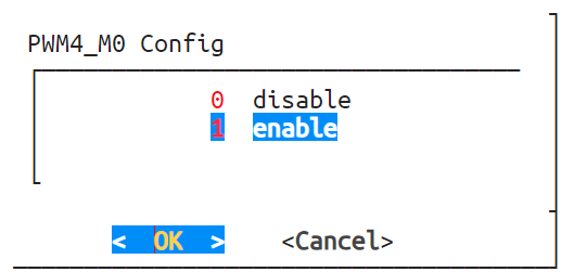
If the pin is already reused for another function and marked, selecting
enablewill display a prompt. The conflicting configuration needs to be disabled for successful enabling.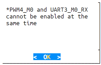
2.3.2 UART Configuration
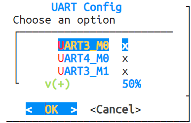
Enter the Compatible Devices -> UART interface, and luckfox-config will display all supported UART configurations.
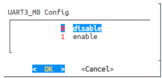
Select the desired option, choose
enableto enable, anddisableto disable. To cancel the configuration, use the direction keys to selectCanceland return to the previous interface.If the pin to be configured is reused for another function and marked, selecting
enablewill display a prompt. The conflicting configuration needs to be disabled for successful enabling.
2.3.3 I2C Configuration
Enter the Advanced Options -> I2C interface, and luckfox-config will display all supported I2C configurations.
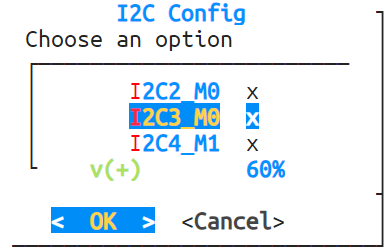
Select the desired option, choose
enableto enable, anddisableto disable. To cancel the configuration, use the direction keys to selectCanceland return to the previous interface. Selectingenablewill enter the speed configuration interface.
In the Luckfox Pico Ultra system, enabling CSI will prevent the configuration of I2C4, and enabling the touch screen will prevent the configuration of I2C3.
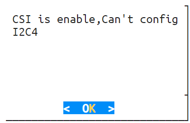
If the pin to be configured is reused for another function and marked, selecting
enablewill display a prompt. The conflicting configuration needs to be disabled for successful enabling.When the touch screen is enabled, I2C3 cannot be configured. When CSI is enabled, I2C4 cannot be configured.
2.3.4 SPI Configuration
Enter the Advanced Options -> SPI interface, and luckfox-config will display all supported SPI configurations.
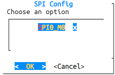
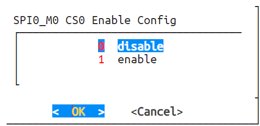
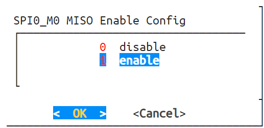
Select the desired option, choose
enableto enable, anddisableto disable. To cancel the configuration, use the direction keys to selectCanceland return to the previous interface.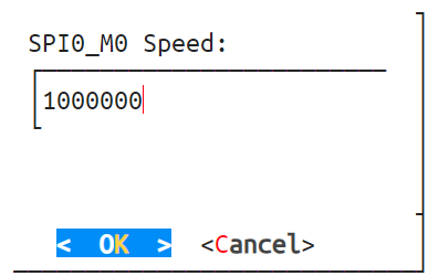
3.If the pin to be configured is reused for another function and marked, selecting enable will display a prompt. The conflicting configuration needs to be disabled for successful enabling.
2.3.5 CSI Configuration
Navigate to Advanced Options -> CSI screen, select
enableto enable and selectdisableto disable.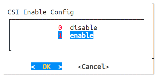
It is recommended to configure CSI once after booting the Luckfox Pico Ultra series to prevent affecting subsequent configurations.
If other I2C4 pins are used, CSI cannot be configured to prevent enabling and disabling CSI from affecting ongoing I2C4 tasks.
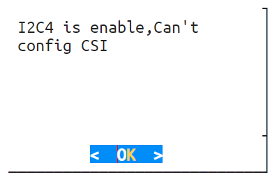
- Note: CSI configuration requires a reboot to take effect.
2.4.6 USB Configuration
- avigate to Advanced Options -> USB screen, configure the USB mode as
peripheralorhost.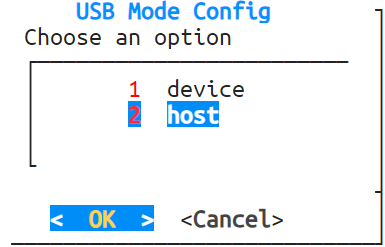
- Note: USB configuration requires a reboot to take effect.