luckfox-config Configuration
The Luckfox Pico pins have multiple multiplexed functions. Depending on project requirements, it is often necessary to adjust the device tree. This section introduces two methods of configuring Luckfox Pico pin multiplexing: at the compilation stage and at runtime. By understanding both, you can flexibly configure Luckfox-Pico pin interface functions.
1. Introduction
luckfox-config is a tool in the Luckfox Pico root filesystem that allows quick configuration of device functions directly on the board.
With the help of the dynamic device tree mechanism and the fdt tool, most device configurations can be applied without recompiling the dtb.
- Terminal Support
| System Type | Buildroot |
|---|---|
| Serial Port | Supported |
| SSH | Supported |
| ADB | Arrow keys not supported |
- Features
| System Type | Buildroot |
|---|---|
| GPIO | Supported |
| PWM | Supported |
| UART | Supported |
| I2C | Supported |
| SPI | Supported |
| FBTFT | Supported only on Luckfox Pico / Plus / Pro / Max |
| RGB | Supported only on Luckfox Pico Ultra / Ultra W |
| TouchScreen | Supported only on Luckfox Pico Ultra / Ultra W |
| USB | Supported |
| CSI | Supported |
2. luckfox-config Setup
Note: luckfox-config configuration is based on the default device tree file. If you have already modified the device tree when building the image, some functions may not work correctly.
2.1 Structure
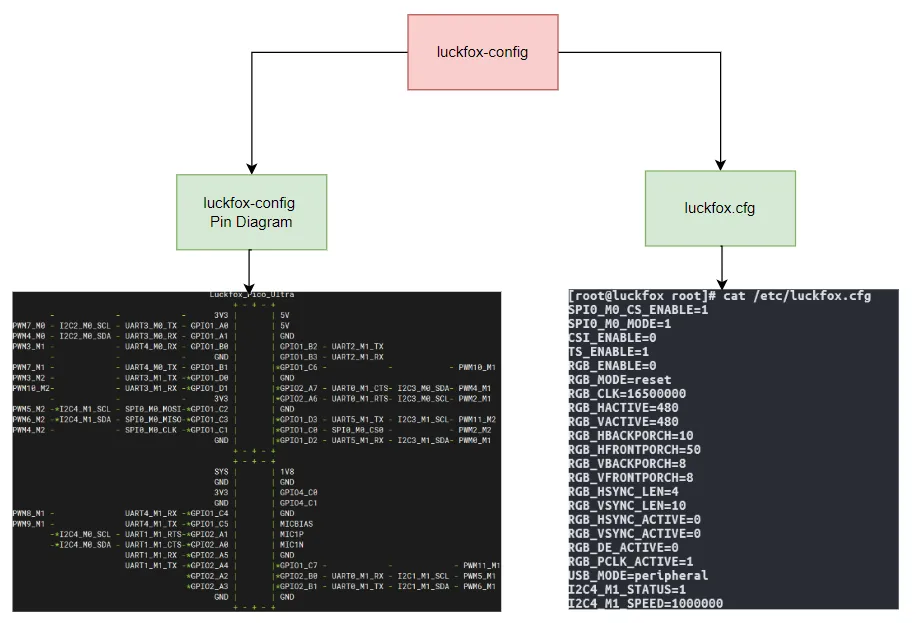
luckfox-config— dynamic device tree configuration tool, provides graphical interactive configuration/etc/luckfox.cfg— stores configuration information; users can edit it manually; configurations are loaded at every root filesystem bootluckfox-config Pin diagram— temporarily stores system configuration key info and provides a visual representation of current pin states
2.2 Basic Usage
- Run the following command on the board terminal to open the graphical configuration interface:
luckfox-config
-The interface looks like this:
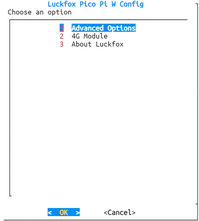
-
Use the ↑ and ↓ keys on the keyboard to navigate menu items, press Enter to enter, use ←, →, or Tab to select the OK and Cancel buttons, press Esc to cancel and return, and use the spacebar to toggle options. Any changes will take effect after a reboot. Note: ADB login does not support arrow keys and Tab. You must use numbers to select options and press Enter to confirm.
-
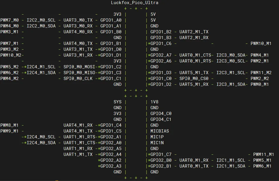
View configuration status. Once a pin is enabled, it will be marked with an “*” and locked. If the newly enabled interface conflicts with locked pins, it cannot be enabled. You can check the current pin lock status in the About menu of
luckfox-configor by running the following command:
luckfox-config show
- If the multiplexed function of a pin is not specified in the pin diagram, the corresponding GPIO will be directly marked.
- For the Luckfox Pico Ultra series, since I2C4 shares pins with the CSI camera, CSI is enabled by default, and the I2C4 pins are configured in
pinctrl-0. Therefore, on first boot, both all I2C4 pins and RGB pins will be marked.
- Save configuration
Common pin multiplexing functions (e.g., PWM, UART, I2C, SPI) take effect immediately after configuration. Devices that do not support dynamic driver detection (e.g., FBTFT, RGB touchscreen, CSI, etc.) require a reboot for the configuration to take effect.
Note: Settings that require a reboot take effect by directly modifying the dtb. The ENABLE state in luckfox.cfg is only for record keeping. Modifying only luckfox.cfg will not actually apply the configuration during load.
- Load configuration
luckfox-config load
Note: Configuration loading is automatically executed during the root filesystem startup stage. It creates a dtboverlay node according to the information in /etc/luckfox.cfg. Normally, you do not need to run this command manually.
2.3 Common Configurations
2.3.1 PWM Configuration
- Go to Advanced Options -> PWM, and
luckfox-configwill display all supported PWM configurations.
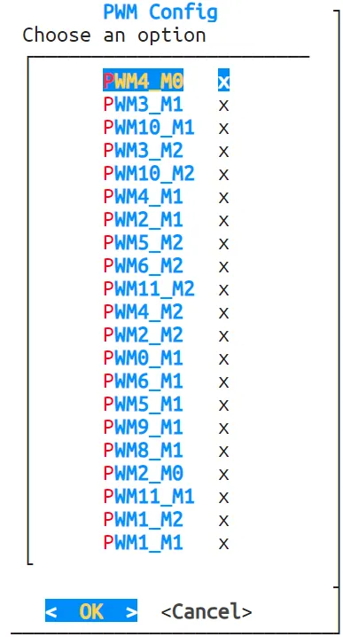
- Select the desired option, choose
enableto enable,disableto disable, or use the arrow keys to selectCancelto return to the previous screen.

- If the pin is already multiplexed for another function and marked, selecting
enablewill display a prompt. You must disable the conflicting configuration before it can be enabled.


2.3.2 UART Configuration
- Go to Advanced Options -> UART, and
luckfox-configwill display all supported UART configurations.
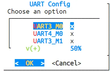
- Select the desired option, choose
enableto enable,disableto disable, or use the arrow keys to selectCancelto return to the previous screen. - If the pin is already multiplexed for another function and marked, selecting
enablewill display a prompt. You must disable the conflicting configuration before it can be enabled.
2.3.3 I2C Configuration
- Go to Advanced Options -> I2C, and
luckfox-configwill display all supported I2C configurations.

- Select the desired option, choose
enableto enable,disableto disable, or use the arrow keys to selectCancelto return. Ifenableis selected, it will enter the speed configuration screen.

- In the Luckfox Pico Ultra system, enabling CSI prevents configuring I2C4, and enabling the touchscreen prevents configuring I2C3.

- If the pin is already multiplexed for another function and marked, selecting
enablewill display a prompt. You must disable the conflicting configuration before it can be enabled. - When the touchscreen is enabled, I2C3 cannot be configured. When CSI is enabled, I2C4 cannot be configured.
2.3.4 SPI Configuration
- Go to Advanced Options -> SPI, and
luckfox-configwill display all supported SPI configurations.

- Select the desired option, choose
enableto enable,disableto disable, or use the arrow keys to selectCancelto return. Ifenableis selected, it will enter the speed configuration screen and pin combination screen, where you can decide whether to enable CS or MISO pins based on your needs.


- If the pin is already multiplexed for another function and marked, selecting
enablewill display a prompt. You must disable the conflicting configuration before it can be enabled.
2.3.5 CSI Configuration
- Go to Advanced Options -> CSI, select
enableto enable ordisableto disable.

- For the Luckfox Pico Pi series, it is recommended to configure CSI once after booting to avoid affecting subsequent configurations.
- If other I2C4 pins are already in use, CSI cannot be configured. This prevents CSI enable/disable actions from interfering with active I2C4 tasks.

- Note: CSI configuration requires a reboot to take effect.
2.4.6 USB Configuration
- Go to Advanced Options -> USB, and configure the USB mode as
peripheralorhost.

- Note: USB configuration requires a reboot to take effect.