LCD Screen
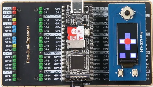
This article aims to provide a detailed guide on how to use the Luckfox Pico to drive a 0.96-inch screen (the only difference from the Plus version is the pin numbering on the right side). We are using the Waveshare Pico-LCD-0.96 LCD display screen. For specific screen parameters, you can refer to the Pico-LCD-0.96 product wiki. You can download the image file and sample program to use directly or follow the steps below to configure it yourself.
1. Compatible Device Configuration
- The Luckfox Pico / Plus / Pro / Max series mainly refers to the pin layout of the Raspberry Pi Pico, and through pin configuration, it can be compatible with some Raspberry Pi Pico peripherals.

- For the list of compatible devices supported by different models of Luckfox Pico, refer to Luckfox-Pico_support-List.
- The compatible device option is essentially a combination of multiple pin configurations, which can simplify the configuration process.
- Due to the lack of io commands to directly configure registers under Ubuntu, the Luckfox Pico cannot configure the pins as default pull-up when configuring the compatible device Pico-LCD, so it cannot properly control the buttons.
- When starting the compatible device configuration, it will overwrite the original configuration. To cancel the compatible device, go to the Advanced Options screen to disable the started device function.
2. Example Program
Pico-LCD-0.96 can achieve display functionality, as well as joystick and button detection. To implement these functions, we need to define pins in the program and implement SPI communication. Afterward, we will compile the program using cross-compilation tools. Let's proceed to examine the specific implementation steps together.
-
Pin Definitions
-
Define the pin numbers in
DEV_Config.h
      #define LCD_DC  (34)
      #define LCD_CS  (48)
      #define LCD_RST (51)
      #define LCD_BL  (4)

      /*PICO*/
      #define KEY_UP_PIN      55 //Rocker up pin number
      #define KEY_DOWN_PIN    134
      #define KEY_LEFT_PIN    137
      #define KEY_RIGHT_PIN   131
      #define KEY_PRESS_PIN   54
      #define KEY1_PIN        57
      #define KEY2_PIN        136
      #define KEY3_PIN        16
      #define KEYA_PIN        57
      #define KEYB_PIN        136
      #define KEYX_PIN        130
      #define KEYY_PIN        132
- Add Read Pin Level Macro Definitions in
DEV_Config.h
      #define GET_KEY_UP              DEV_Digital_Read(KEY_UP_PIN)  //Read the rocker up pin level
      #define GET_KEY_DOWN            DEV_Digital_Read(KEY_DOWN_PIN)
      #define GET_KEY_LEFT            DEV_Digital_Read(KEY_LEFT_PIN)
      #define GET_KEY_RIGHT           DEV_Digital_Read(KEY_RIGHT_PIN)
      #define GET_KEY_PRESS           DEV_Digital_Read(KEY_PRESS_PIN)
      #define GET_KEY1                DEV_Digital_Read(KEY1_PIN)
      #define GET_KEY2                DEV_Digital_Read(KEY2_PIN)
      #define GET_KEY3                DEV_Digital_Read(KEY3_PIN)
      #define GET_KEYA                DEV_Digital_Read(KEYA_PIN)
      #define GET_KEYB                DEV_Digital_Read(KEYB_PIN)
      #define GET_KEYX                DEV_Digital_Read(KEYX_PIN)
      #define GET_KEYY                DEV_Digital_Read(KEYY_PIN)
- Initialize GPIO in
DEV_GPIO_InitFunction
      static void DEV_GPIO_Init(void)
      {
          DEV_GPIO_Mode(LCD_CS, 1);
          DEV_GPIO_Mode(LCD_RST, 1);
          DEV_GPIO_Mode(LCD_DC, 1);
          DEV_GPIO_Mode(LCD_BL, 1);

          DEV_GPIO_Mode(KEY_UP_PIN, 0); //Joystick up pin initialized as input
          DEV_GPIO_Mode(KEY_DOWN_PIN, 0);
          DEV_GPIO_Mode(KEY_LEFT_PIN, 0);
          DEV_GPIO_Mode(KEY_RIGHT_PIN, 0);
          DEV_GPIO_Mode(KEY_PRESS_PIN, 0);
          DEV_GPIO_Mode(KEY1_PIN, 0);
          DEV_GPIO_Mode(KEY2_PIN, 0);
          DEV_GPIO_Mode(KEY3_PIN, 0);
          DEV_GPIO_Mode(KEYA_PIN, 0);
          DEV_GPIO_Mode(KEYB_PIN, 0);
          DEV_GPIO_Mode(KEYX_PIN, 0);
          DEV_GPIO_Mode(KEYY_PIN, 0);
          LCD_CS_1;
          LCD_BL_1;
      }
- Evaluate Pin Levels in
Pico_LCD_0in96_test.c
      /* Key */
      while(1)
      {
          /* Check if the pin level is low */
          if(GET_KEY_UP == 0){
              /* Add operations for joystick up */
           }else{
              /* Add operations when joystick is not up */
          }

          if(GET_KEY_RIGHT == 0){
              /* Add operations for joystick right */
          }else{
              /* Add operations when joystick is not right */
          }
      }
-
SPI Communication
-
Request SPI Resources in the
DEV_ModuleInitFunction
DEV_HARDWARE_SPI_begin("/dev/spidev0.0");
- Initialization
Initialize the LCD by calling the PICO_LCD_0IN96_Init function in the main function.
      void PICO_LCD_0IN96_Init(void)
      {
          PICO_LCD_0IN96_Reset();

          //************* Start Initial Sequence **********//
          PICO_LCD_0IN96_Write_Command(0x11);//Sleep exit
          DEV_Delay_ms(120);
          PICO_LCD_0IN96_Write_Command(0x21);
          PICO_LCD_0IN96_Write_Command(0x21);

          PICO_LCD_0IN96_Write_Command(0xB1);
          PICO_LCD_0IN96_WriteData_Byte(0x05);
          PICO_LCD_0IN96_WriteData_Byte(0x3A);

          ...
      }
- Sending Data
In the PICO_LCD_0IN96_Write_Command function, you can lower the LCD_DC pin to indicate that you're sending a command, and then use the DEV_SPI_WriteByte function to send data to the LCD.
      static void PICO_LCD_0IN96_Write_Command(UBYTE data)
      {
          DEV_Digital_Write(LCD_DC, 0);
          DEV_SPI_WriteByte(data);
      }
In the PICO_LCD_0IN96_WriteData_Byte function, set the LCD_DC pin to high, indicating data transmission, and then call the DEV_SPI_WriteByte function to send data to the LCD.
      static void PICO_LCD_0IN96_WriteData_Byte(UBYTE data)
      {
          DEV_Digital_Write(LCD_DC, 1);
          DEV_SPI_WriteByte(data);
      }
-
Cross Compilation
-
Specify the Cross Compilation Tool
Users should move the entire "c" folder to the virtual machine and edit the Makefile file within the "c" folder. Modify the content after CC= in the Makefile to specify the cross-compilation tool.
Replace <SDK Directory> with your own SDK path in the Makefile, for example, /home/luckfox/luckfox-pico/.
      DIR_Config   = ./lib/Config
      DIR_EPD      = ./lib/LCD
      DIR_FONTS    = ./lib/Fonts
      DIR_GUI      = ./lib/GUI
      DIR_Examples = ./examples
      DIR_BIN      = ./bin

      OBJ_C = $(wildcard ${DIR_EPD}/*.c ${DIR_Config}/*.c ${DIR_GUI}/*.c ${DIR_Examples}/*.c ${DIR_FONTS}/*.c)
      OBJ_O = $(patsubst %.c,${DIR_BIN}/%.o,$(notdir ${OBJ_C}))

      TARGET = main

      USELIB = USE_DEV_LIB
      DEBUG = -D $(USELIB)
      ifeq ($(USELIB), USE_DEV_LIB)
          LIB = -lpthread -lm
      endif


      CC = <SDK Directory>/tools/linux/toolchain/arm-rockchip830-linux-uclibcgnueabihf/bin/arm-rockchip830-linux-uclibcgnueabihf-gcc
      MSG = -g -O0 -Wall
      CFLAGS += $(MSG) $(DEBUG)

      ${TARGET}:${OBJ_O}
          $(CC) $(CFLAGS) $(OBJ_O) -o $@ $(LIB)

      ${DIR_BIN}/%.o:$(DIR_Examples)/%.c
          $(CC) $(CFLAGS) -c  $< -o $@ -I $(DIR_Config) -I $(DIR_GUI) -I $(DIR_EPD)

      ${DIR_BIN}/%.o:$(DIR_EPD)/%.c
          $(CC) $(CFLAGS) -c  $< -o $@ -I $(DIR_Config)

      ${DIR_BIN}/%.o:$(DIR_FONTS)/%.c
          $(CC) $(CFLAGS) -c  $< -o $@

      ${DIR_BIN}/%.o:$(DIR_GUI)/%.c
          $(CC) $(CFLAGS) -c  $< -o $@ -I $(DIR_Config)  -I $(DIR_EPD) -I $(DIR_Examples)

      ${DIR_BIN}/%.o:$(DIR_Config)/%.c
          $(CC) $(CFLAGS) -c  $< -o $@ $(LIB)

      clean :
          rm $(DIR_BIN)/*.*
          rm $(TARGET)
- Compile the Program
After editing the Makefile , use the 'make' command to cross-compile the program.
luckfox@luckfox:~/c$ make
Once cross-compilation is successful, an executable file named main will be generated in the current directory.
      luckfox@luckfox:~/c$ ls
      bin  examples  lib  main  Makefile  pic  readme_CN.txt  readme_EN.txt
3. Achieving the Desired Outcomes
- Transferring Compiled Files to the Development Board
To start, transfer the entire "c" folder from the virtual machine to your Windows computer. Next, use either TFTP or ADB to move the files to the development board. Here are the steps for using ADB to transfer files from Windows to the development board:
   adb push [path_to_files] [board_storage_path]

   Example: (Transferring the "c" folder from the current directory to the root directory of the development board)
   adb push c /
- Running the Program
After adjusting the permissions of the main file, execute the program:
   #cd c/
   #chmod 777 main
   #./main 0.96
- Experimental Observations
GUI Interface
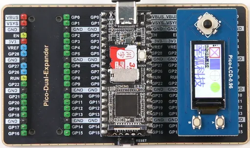
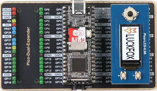
Image Display
Joystick and Button Operations