OLED Display (Python)
This article aims to provide a detailed guide on how to use Luckfox Pico to drive a 1.5-inch screen. We use Waveshare's 1.5inch OLED Module. For specific parameters of the screen, you can refer to the product wiki of 1.5inch OLED Module. You can download the image files and sample programs for direct use or follow the steps below to configure it yourself.
1. Pin Mapping
Ensuring the proper functionality of all pins involved in OLED communication is a basic requirement for driving the OLED. The default factory image for all models of Luckfox Pico boards enables SPI0 and I2C3, which can be used directly. Additionally, when using SPI communication, three general-purpose IO pins are needed to control the CS, DC, and RST pins of the OLED module.
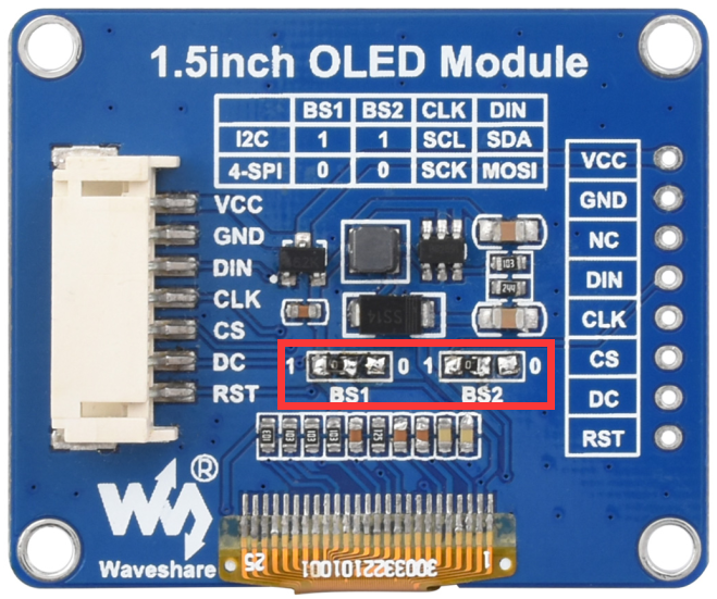
Note: The module uses 4-wire SPI communication by default when shipped from the factory, that is, BS is connected to 0 by default. If I2C communication is used, BS needs to be connected to 1 (1 and 0 do not all represent levels, but are just the welding method of resistor connection).
Pico-OLED-1.5
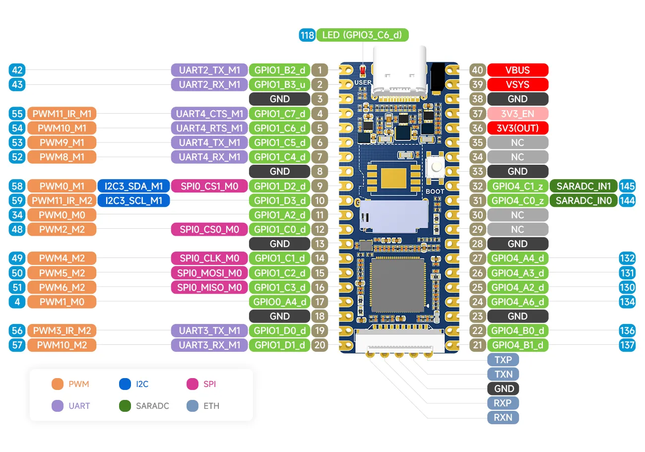
Luckfox Pico
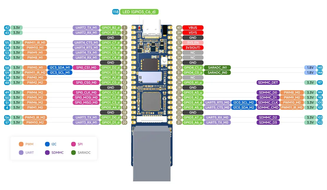
Luckfox Pico Plus
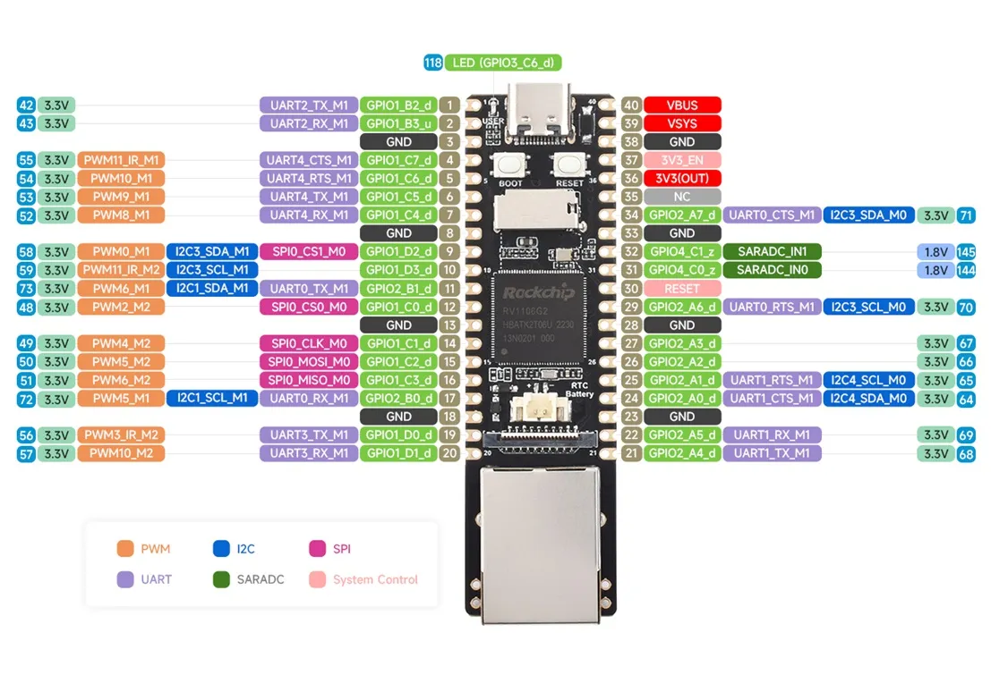
Luckfox Pico Pro/Max
Connection pin correspondence
- I2C
| 1.5inch OLED Module | Luckfox Pico Pin | Function |
|---|---|---|
| VCC | 3V3 | Power Input |
| GND | GND | Power Ground |
| DIN | I2C3_SDA | I2C Data Input |
| CLK | I2C3_SCL | I2C Clock |
- SPI
| 1.5inch OLED Module | Luckfox Pico Pin | Function |
|---|---|---|
| VCC | 3V3 | Power Input |
| GND | GND | Power Ground |
| DIN | SPI1_MOSI | Master Output/Slave Input |
| CLK | SPI1_CLK | SPI Clock |
| CS | GPIO1_C7(55) | Chip Select |
| DC | GPIO1_C6(54) | Data/Command Select |
| RST | GPIO1_C4(52) | Reset |
1. Compatible Device Configuration
- The Luckfox Pico / Plus / Pro / Max series mainly refers to the pin layout of the Raspberry Pi Pico, and through pin configuration, it can be compatible with some Raspberry Pi Pico peripherals.

- For the list of compatible devices supported by different models of Luckfox Pico, refer to Luckfox-Pico_support-List.
- The compatible device option is essentially a combination of multiple pin configurations, which can simplify the configuration process.
- Due to the lack of io commands to directly configure registers under Ubuntu, the Luckfox Pico cannot configure the pins as default pull-up when configuring the compatible device Pico-LCD, so it cannot properly control the buttons.
- When starting the compatible device configuration, it will overwrite the original configuration. To cancel the compatible device, go to the Advanced Options screen to disable the started device function.
3. Run the Program
- Program Download
- File Transfer
After decompressing, transfer the entire OLED_1in5_Code folder to the development board via TFTP or ADB. Here are the steps to transfer the folder from Windows to the development board using ADB:
   adb push path_to_file development_board_storage_path

   eg: (Transfer the OLED_1in5_Code folder from the current directory to the root directory of the development board)
   adb push OLED_1in5_Code /
- Run the Program
   # cd /OLED_1in5_Code
   # python3 OLED_1in5_spi.py