OLED Display (C Language)
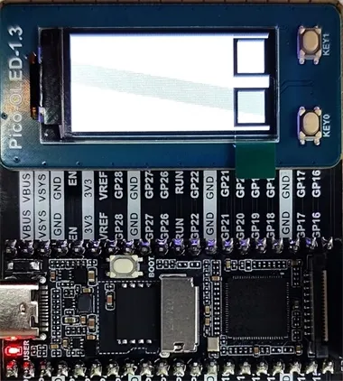
This article aims to provide a detailed guide on how to use Luckfox Pico Plus to drive a 1.3-inch screen (the Pico version differs in right-side pin numbering). We are using Waveshare's Pico-OLED-1.3. For specific screen parameters, you can refer to the Pico-OLED-1.3 product wiki. You can download the image file and sample program to use directly or follow the steps below to configure it yourself.
1. Pin Mapping
Ensuring that all pins used for OLED communication function properly is a basic requirement for driving the OLED. Therefore, we need to configure pin functionality in the device tree file. Before that, we need to determine the pins on Luckfox Pico Plus to which the Pico-OLED-1.3 is connected. Let's take the example of user button 0 on Pico-OLED-1.3, which corresponds to pin GP15. On Luckfox Pico Plus, its pin number is 20, GPIO pin name is GPIO1_D1_d, and its pin number is 57.
Pico-OLED-1.3

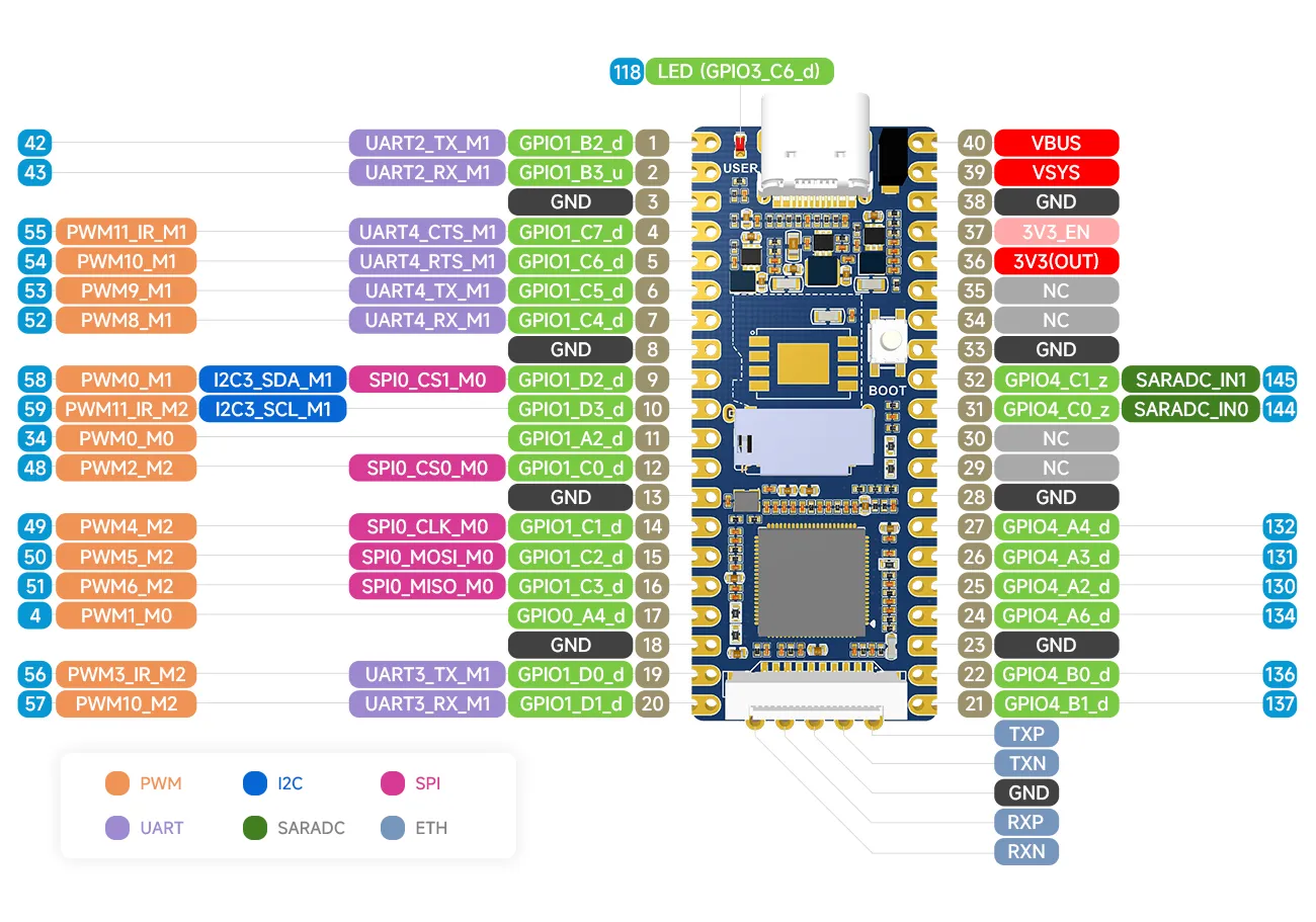
Luckfox Pico
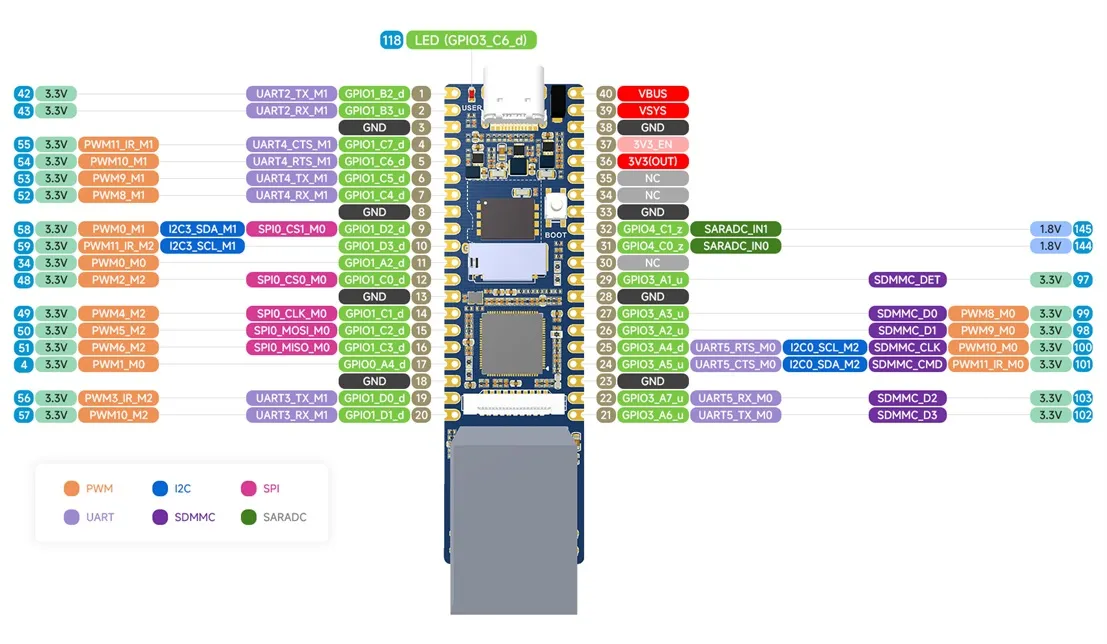
Luckfox Pico Plus
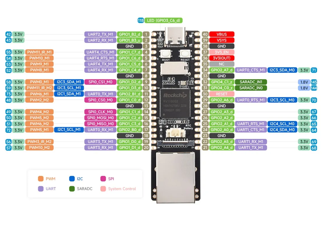
Luckfox Pico Pro/Max
2. Compatible Device Configuration
- The Luckfox Pico / Plus / Pro / Max series mainly refers to the pin layout of the Raspberry Pi Pico, and through pin configuration, it can be compatible with some Raspberry Pi Pico peripherals.

- For the list of compatible devices supported by different models of Luckfox Pico, refer to Luckfox-Pico_support-List.
- The compatible device option is essentially a combination of multiple pin configurations, which can simplify the configuration process.
- Due to the lack of io commands to directly configure registers under Ubuntu, the Luckfox Pico cannot configure the pins as default pull-up when configuring the compatible device Pico-LCD, so it cannot properly control the buttons.
- When starting the compatible device configuration, it will overwrite the original configuration. To cancel the compatible device, go to the Advanced Options screen to disable the started device function.
3. Example Program
Pico-OLED-1.3 can achieve display and key detection functions. To implement these features, we need to define pins and implement SPI/I2C communication in the program, and then compile the program using cross-compilation tools. Next, let's take a look at the specific implementation steps.
-
Pin Definitions
-
Define the pin numbers in
DEV_Config.h
      #define OLED_DC_PIN     34
      #define OLED_RST_PIN   51

      /*PICO*/
      // #define KEY0_PIN        57
      // #define KEY1_PIN        136

      /*PLUS*/
      #define KEY0_PIN        57
      #define KEY1_PIN        103
- Add Read Pin Level Macro Definitions in
DEV_Config.h
      #define GET_KEY0         DEV_Digital_Read(KEY0_PIN)
      #define GET_KEY1         DEV_Digital_Read(KEY1_PIN)
- Initialize GPIO in
DEV_GPIO_InitFunction
      static void DEV_GPIO_Init(void)
      {
          DEV_GPIO_Mode(OLED_RST_PIN, 1);
          DEV_GPIO_Mode(OLED_DC_PIN, 1);
          DEV_GPIO_Mode(KEY0_PIN, 0);
          DEV_GPIO_Mode(KEY1_PIN, 0);
      }
- Evaluate Pin Levels in
OLED_1in3_c_test.c
      /* Key */
      while(1)
      {
          /* Check if the pin level is low */
          if(GET_KEY1 == 0){
              /* Add operations to perform when user presses key 1 here */
           }else{
              /* Add operations to perform when user releases key 1 here */
          }

          if(GET_KEY0 == 0){
              /* Add operations to perform when user presses key 0 here */
          }else{
              /* Add operations to perform when user releases key 0 here */
          }
      }
-
SPI/I2C Communication
-
Select the communication method in
DEV_Config.h. By default, SPI communication is used. When using I2C communication, you need to modify the resistors on the back of Pico-OLED-1.3.
      #define USE_SPI  1
      #define USE_IIC  0
- Request SPI/I2C resources in the
DEV_ModuleInitfunction.
      UBYTE DEV_ModuleInit(void)
      {
       #ifdef USE_DEV_LIB

	DEV_GPIO_Init();
          #if USE_SPI
              printf("USE_SPI\r\n");
              DEV_HARDWARE_SPI_beginSet("/dev/spidev0.0",SPI_MODE_3,10000000);
          #elif USE_IIC
              printf("USE_IIC\r\n");
              OLED_DC_0;
              OLED_CS_0;
              DEV_HARDWARE_I2C_begin("/dev/i2c-3");
              DEV_HARDWARE_I2C_setSlaveAddress(0x3c);
          #endif

      #endif
          return 0;
      }
- Initialization
Call the OLED_1in3_C_Init function to initialize the OLED in the main function.
      void OLED_1in3_C_Init()
      {
          //Hardware reset
          OLED_Reset();

          //Set the initialization register
          OLED_InitReg();
      }
- Sending Data
In the OLED_WriteReg function, pull the OLED_DC pin low to indicate command transmission, then use the DEV_SPI_WriteByte or I2C_Write_Byte function to send data to the OLED.
      static void OLED_WriteReg(uint8_t Reg)
      {
      #if USE_SPI
          OLED_DC_0;
          DEV_SPI_WriteByte(Reg);
      #elif USE_IIC
          I2C_Write_Byte(Reg,IIC_CMD);
      #endif
      }
In the OLED_WriteData function, set the OLED_DC pin high to indicate data transmission, then use the DEV_SPI_WriteByte or I2C_Write_Byte function to send data to the OLED.
      static void OLED_WriteData(uint8_t Data)
      {
      #if USE_SPI
          OLED_DC_1;
          DEV_SPI_WriteByte(Data);
      #elif USE_IIC
          I2C_Write_Byte(Data,IIC_RAM);
      #endif
      }
-
Cross Compilation
-
Specify the Cross Compilation Tool
Users should move the entire "c" folder to the virtual machine and edit the Makefile file within the "c" folder. Modify the content after CC= in the Makefile to specify the cross-compilation tool.
Replace <SDK Directory> with your own SDK path in the Makefile, for example, /home/luckfox/luckfox-pico/.
      DIR_Config   = ./lib/Config
      DIR_EPD      = ./lib/OLED
      DIR_FONTS    = ./lib/Fonts
      DIR_GUI      = ./lib/GUI
      DIR_Examples = ./examples
      DIR_BIN      = ./bin

      OBJ_C = $(wildcard ${DIR_EPD}/*.c ${DIR_Config}/*.c ${DIR_GUI}/*.c ${DIR_Examples}/*.c ${DIR_FONTS}/*.c)
      OBJ_O = $(patsubst %.c,${DIR_BIN}/%.o,$(notdir ${OBJ_C}))

      TARGET = main

      USELIB = USE_DEV_LIB
      DEBUG = -D $(USELIB)
      ifeq ($(USELIB), USE_DEV_LIB)
          LIB = -lpthread -lm
      endif


      CC = <SDK Directory>/tools/linux/toolchain/arm-rockchip830-linux-uclibcgnueabihf/bin/arm-rockchip830-linux-uclibcgnueabihf-gcc
      MSG = -g -O0 -Wall
      CFLAGS += $(MSG) $(DEBUG)

      ${TARGET}:${OBJ_O}
	$(CC) $(CFLAGS) $(OBJ_O) -o $@ $(LIB)

      ${DIR_BIN}/%.o:$(DIR_Examples)/%.c
	$(CC) $(CFLAGS) -c  $< -o $@ -I $(DIR_Config) -I $(DIR_GUI) -I $(DIR_EPD)

      ${DIR_BIN}/%.o:$(DIR_EPD)/%.c
	$(CC) $(CFLAGS) -c  $< -o $@ -I $(DIR_Config)

      ${DIR_BIN}/%.o:$(DIR_FONTS)/%.c
	$(CC) $(CFLAGS) -c  $< -o $@

      ${DIR_BIN}/%.o:$(DIR_GUI)/%.c
	$(CC) $(CFLAGS) -c  $< -o $@ -I $(DIR_Config)  -I $(DIR_EPD) -I $(DIR_Examples)

      ${DIR_BIN}/%.o:$(DIR_Config)/%.c
	$(CC) $(CFLAGS) -c  $< -o $@ $(LIB)


      clean :
	rm $(DIR_BIN)/*.*
	rm $(TARGET)
- Compile the Program
After editing the Makefile , use the 'make' command to cross-compile the program.
luckfox@luckfox:~/c$ make
Once cross-compilation is successful, an executable file named main will be generated in the current directory.
      luckfox@luckfox:~/c$ ls
      bin  examples  lib  main  Makefile  pic  readme_CN.txt  readme_EN.txt
4. Achieving the Desired Outcomes
- Transferring Compiled Files to the Development Board
To start, transfer the entire "c" folder from the virtual machine to your Windows computer. Next, use either TFTP or ADB to move the files to the development board. Here are the steps for using ADB to transfer files from Windows to the development board:
   adb push [path_to_files] [board_storage_path]

   Example: (Transferring the "c" folder from the current directory to the root directory of the development board)
   adb push c /
- Running the Program
After adjusting the permissions of the main file, execute the program:
   #cd c/
   #chmod 777 main
   #./main
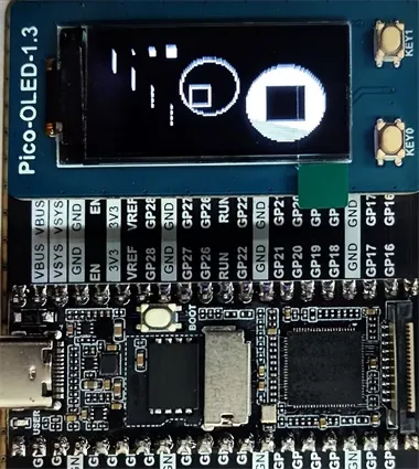
- Experimental Observations
GUI Interface 1
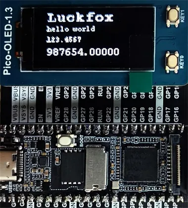
GUI Interface 2
GUI Interface 3
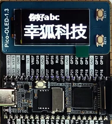
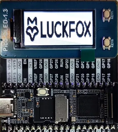
Image Display
Key Operations