ResTouch LCD
This article aims to provide a detailed guide on how to use Luckfox Pico Plus to drive a 3.5-inch screen. We will be using Waveshare's Pico-ResTouch-LCD-3.5 resistive touchscreen expansion board. You can find specific details about the screen in the product wiki for Pico-ResTouch-LCD-3.5. You can download the image file and sample program to use directly or follow the steps below to configure it yourself.
1. Compatible Device Configuration
- The Luckfox Pico / Plus / Pro / Max series mainly refers to the pin layout of the Raspberry Pi Pico, and through pin configuration, it can be compatible with some Raspberry Pi Pico peripherals.

- For the list of compatible devices supported by different models of Luckfox Pico, refer to Luckfox-Pico_support-List.
- The compatible device option is essentially a combination of multiple pin configurations, which can simplify the configuration process.
- Due to the lack of io commands to directly configure registers under Ubuntu, the Luckfox Pico cannot configure the pins as default pull-up when configuring the compatible device Pico-LCD, so it cannot properly control the buttons.
- When starting the compatible device configuration, it will overwrite the original configuration. To cancel the compatible device, go to the Advanced Options screen to disable the started device function.
2. Example Program
The Pico-ResTouch-LCD-3.5 resistive touch screen expansion board features the XPT2046 resistive touch control chip and a Micro SD card slot, allowing for display, touch, and SD card reading functionalities. To achieve these functions, we need to define pins in the program and implement SPI communication, followed by compiling the program using a cross-compilation tool. Let's delve into the specific implementation steps.
-
Pin Definitions
-
Define the pin numbers in
DEV_Config.h
      #define LCD_DC_PIN   (34)
      #define LCD_CS_PIN   (48)   //Define LCD chip select pin number
      #define LCD_RST_PIN  (57)
      #define LCD_BL_PIN   (4)
      #define TP_CS_PIN    (102)
      #define TP_IRQ_PIN   (103)
      #define SD_CS_PIN    (97)
- Add Control Pin Level Macro Definitions in
DEV_Config.h
      //LCD
      #define LCD_CS_0        DEV_Digital_Write(LCD_CS_PIN,0)  //LCD chip select pin pulled low
      #define LCD_CS_1        DEV_Digital_Write(LCD_CS_PIN,1)  //LCD chip select pin set high
      #define LCD_RST_0       DEV_Digital_Write(LCD_RST_PIN,0)
      #define LCD_RST_1       DEV_Digital_Write(LCD_RST_PIN,1)
      #define LCD_DC_0        DEV_Digital_Write(LCD_DC_PIN,0)
      #define LCD_DC_1        DEV_Digital_Write(LCD_DC_PIN,1)
      #define LCD_BL_0        DEV_Digital_Write(LCD_BL_PIN,0)
      #define LCD_BL_1        DEV_Digital_Write(LCD_BL_PIN,1)

      //TP
      #define TP_CS_0     DEV_Digital_Write(TP_CS_PIN,0)
      #define TP_CS_1     DEV_Digital_Write(TP_CS_PIN,1)

      //SD
      #define SD_CS_0     DEV_Digital_Write(SD_CS_PIN,0)
      #define SD_CS_1     DEV_Digital_Write(SD_CS_PIN,1)
- Initialize GPIO in
DEV_GPIO_InitFunction
      static void DEV_GPIO_Init(void)
      {
          DEV_GPIO_Mode(LCD_CS_PIN, 1);   //LCD chip select pin initialized as output
          DEV_GPIO_Mode(LCD_RST_PIN, 1);
          DEV_GPIO_Mode(LCD_DC_PIN, 1);
          DEV_GPIO_Mode(LCD_BL_PIN, 1);
          DEV_GPIO_Mode(TP_CS_PIN, 1);
          DEV_GPIO_Mode(SD_CS_PIN, 1);
          DEV_GPIO_Mode(TP_IRQ_PIN, 0);

          LCD_CS_1; //LCD chip select pin set high
          TP_CS_1;
          SD_CS_1;
          LCD_BL_0;
      }
-
SPI Communication
-
Request SPI Resources in the
DEV_ModuleInitFunction
DEV_HARDWARE_SPI_begin("/dev/spidev0.0");
- Initialization
      LCD_SCAN_DIR lcd_scan_dir = SCAN_DIR_DFT; // Choose the rotation angle

      SD_Init();                   // Initialize Micro SD
      LCD_Init(lcd_scan_dir, 800); // Initialize LCD
      TP_Init(lcd_scan_dir);       // Initialize touch IC
The sample program is also compatible with the Pico-ResTouch-LCD-2.8 resistive touch screen expansion board. In the program, the LCD model is determined by calling the LCD_Read_Id function to read the ID value.
      static void LCD_InitReg(void)
      {
          id = LCD_Read_Id();
          if(LCD_2_8 == id){
              // Initialize for 2.8-inch LCD
          }else{
              // Initialize for 3.5-inch LCD
          }
      }
In the LCD_Read_Id function, the DEV_HARDWARE_SPI_TransferByte function is called to send and receive data to and from the LCD.
      uint8_t LCD_Read_Id(void)
      {
          uint8_t reg = 0xDC;
          uint8_t tx_val = 0x00;
          uint8_t rx_val;

          DEV_Digital_Write(LCD_CS_PIN, 0);          // Initiate communication, pull down LCD_CS_PIN
          DEV_Digital_Write(LCD_DC_PIN, 0);          // Pull down LCD_DC_PIN to indicate command transmission
          DEV_HARDWARE_SPI_TransferByte(reg);        // Send command to LCD
          rx_val = DEV_HARDWARE_SPI_TransferByte(tx_val); // Send command to LCD and receive the return value
          DEV_Digital_Write(LCD_CS_PIN, 1);          // End communication, pull up LCD_CS_PIN

          return rx_val; // Return the data read
      }
-
Cross Compilation
-
Specify the Cross Compilation Tool
Users should move the entire "c" folder to the virtual machine and edit the Makefile file within the "c" folder. Modify the content after CC= in the Makefile to specify the cross-compilation tool.
Replace <SDK Directory> with your own SDK path in the Makefile, for example, /home/luckfox/luckfox-pico/.
      DIR_Config   = ./lib/Config
      DIR_EPD      = ./lib/LCD
      DIR_FONTS    = ./lib/Fonts
      DIR_GUI      = ./lib/GUI
      DIR_Examples = ./examples
      DIR_FATFS    = ./lib/Fatfs
      DIR_SDCARD    = ./lib/Sdcard
      DIR_BIN      = ./bin

      OBJ_C = $(wildcard ${DIR_EPD}/*.c ${DIR_Config}/*.c ${DIR_GUI}/*.c ${DIR_Examples}/*.c ${DIR_FONTS}/*.c ${DIR_FATFS}/*.c ${DIR_SDCARD}/*.c)
      OBJ_O = $(patsubst %.c,${DIR_BIN}/%.o,$(notdir ${OBJ_C}))

      TARGET = main

      USELIB = USE_DEV_LIB
      DEBUG = -D $(USELIB)
      ifeq ($(USELIB), USE_DEV_LIB)
          LIB = -lpthread -lm
      endif


      CC = <SDK Directory>/tools/linux/toolchain/arm-rockchip830-linux-uclibcgnueabihf/bin/arm-rockchip830-linux-uclibcgnueabihf-gcc
      MSG = -g -O0 -Wall
      CFLAGS += $(MSG) $(DEBUG)

      ${TARGET}:${OBJ_O}
	$(CC) $(CFLAGS) $(OBJ_O) -o $@ $(LIB)

      ${DIR_BIN}/%.o:$(DIR_Examples)/%.c
	$(CC) $(CFLAGS) -c  $< -o $@ -I $(DIR_Config) -I $(DIR_GUI) -I $(DIR_EPD)

      ${DIR_BIN}/%.o:$(DIR_EPD)/%.c
	$(CC) $(CFLAGS) -c  $< -o $@ -I $(DIR_Config)  -I $(DIR_GUI) -I $(DIR_FATFS)

      ${DIR_BIN}/%.o:$(DIR_FONTS)/%.c
	$(CC) $(CFLAGS) -c  $< -o $@

      ${DIR_BIN}/%.o:$(DIR_GUI)/%.c
	$(CC) $(CFLAGS) -c  $< -o $@ -I $(DIR_Config)  -I $(DIR_EPD) -I $(DIR_Examples) -I $(DIR_FONTS)

      ${DIR_BIN}/%.o:$(DIR_Config)/%.c
	$(CC) $(CFLAGS) -c  $< -o $@ $(LIB)

      ${DIR_BIN}/%.o:$(DIR_SDCARD)/%.c
	$(CC) $(CFLAGS) -c  $< -o $@ -I $(DIR_Config)

      ${DIR_BIN}/%.o:$(DIR_FATFS)/%.c
	$(CC) $(CFLAGS) -c  $< -o $@ -I $(DIR_Config) -I $(DIR_EPD) -I $(DIR_FONTS) -I $(DIR_SDCARD) -I $(DIR_GUI)

      clean :
	rm $(DIR_BIN)/*.*
	rm $(TARGET)
- Compile the Program
After editing the Makefile , use the 'make' command to cross-compile the program.
luckfox@luckfox:~/c$ make
Once cross-compilation is successful, an executable file named main will be generated in the current directory.
      luckfox@luckfox:~/c$ ls
      bin  examples  lib  main  Makefile  pic  readme_CN.txt  readme_EN.txt
3. Achieving the Desired Outcomes
- Transferring Compiled Files to the Development Board
To start, transfer the entire "c" folder from the virtual machine to your Windows computer. Next, use either TFTP or ADB to move the files to the development board. Here are the steps for using ADB to transfer files from Windows to the development board:
   adb push [path_to_files] [board_storage_path]

   Example: (Transferring the "c" folder from the current directory to the root directory of the development board)
   adb push c /
- Running the Program
After adjusting the permissions of the main file, execute the program:
   #cd c/
   #chmod 777 main
   #./main
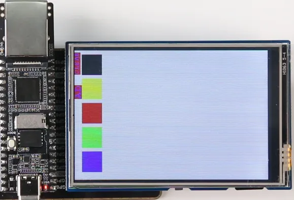
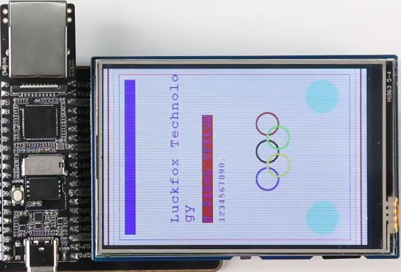
- Experimental Observations
GUI Interface
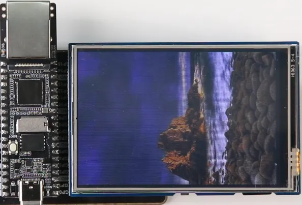
Read images from the SD card and display them
Touch interface